EN
EN




- Overview
- Specifications
- Description
- Applications
- Features
- Contact and Solenoid Outputs
- Installation and Environmental Considerations
- Application software
- Frequently Asked Questions
- Recommended Products
Overview
Place of Origin: |
USA |
Brand Name: |
GE |
Model Number: |
DS200FSAAG2ABA DS2020FECNRX010A |
Packaging Details: |
Original new Factory Sealed |
Delivery Time: |
5-7 days |
Payment Terms: |
T/T |
Supply Ability: |
In stock |
Specifications
|
Part Number: |
DS200FSAAG2ABA / DS2020FECNRX010A |
|
Manufacturer: |
General Electric (GE) |
|
System: |
Drive Control System |
|
Product Type: |
Field Supply Amplifier Board |
|
Function: |
Field signal amplification and voltage regulation |
|
Application: |
Turbine control systems |
|
Power Requirements: |
+5 V DC, 6 A |
|
Power Supply Voltage: |
28 V DC |
|
Relay Channels: |
12 |
|
NRX Current Capability: |
24 A |
|
Shunt Rating: |
10 A |
|
Connectors: |
Multiple prong-type connectors |
|
Jumpers: |
7 (JP1–JP7) |
|
Terminal Blocks: |
2 blocks, 3 terminals each |
|
Mounting Method: |
Standoffs mounting |
|
Cooling Method: |
Natural airflow cooling |
|
Heat Management: |
Requires adequate ventilation or fans |
|
Ventilation Option: |
Hood-assisted heat exhaust |
|
Operating Environment: |
Industrial power generation and distribution |
|
Protection Feature: |
Electrical overload protection |
|
Installation Requirement: |
Adequate spacing for heat dissipation |
|
Dimensions: |
28 x 10.2 x 12 cm |
|
Weight: |
2.22 kg |
|
Country of Manufacture: |
United States (USA) |
Description
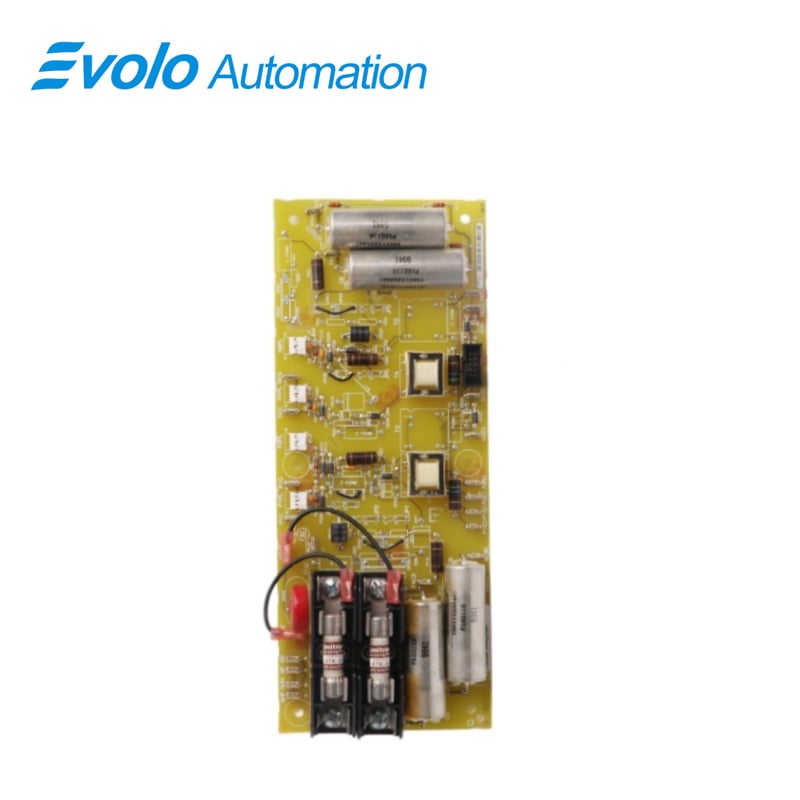
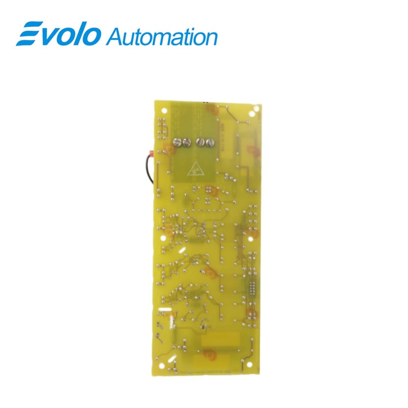
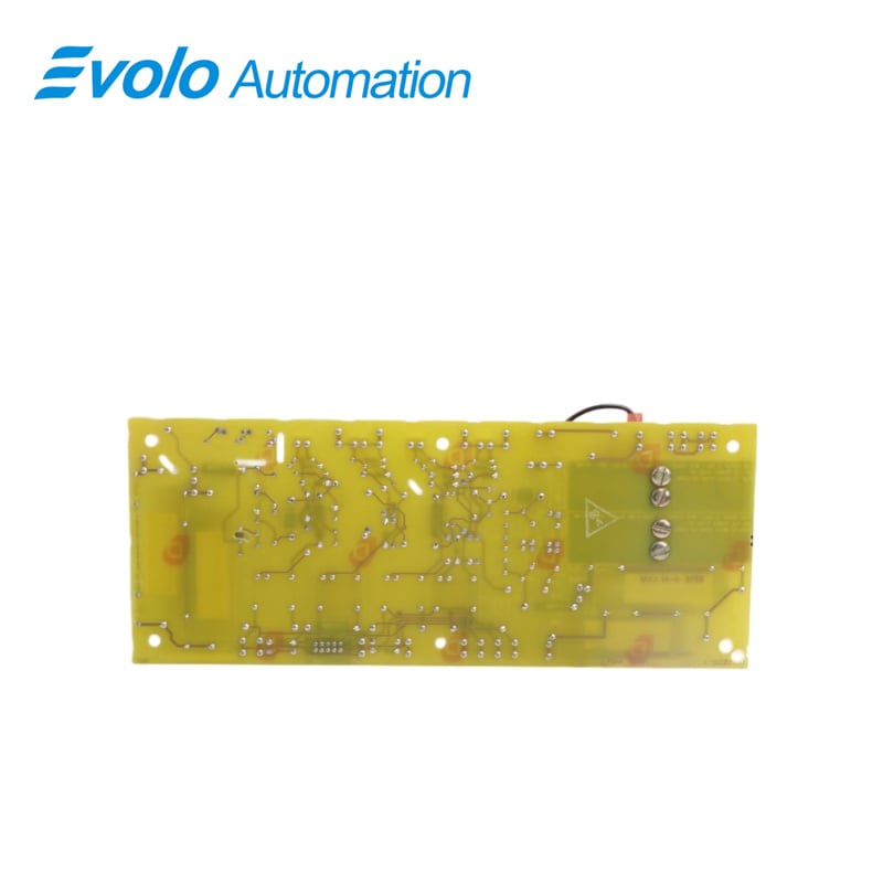
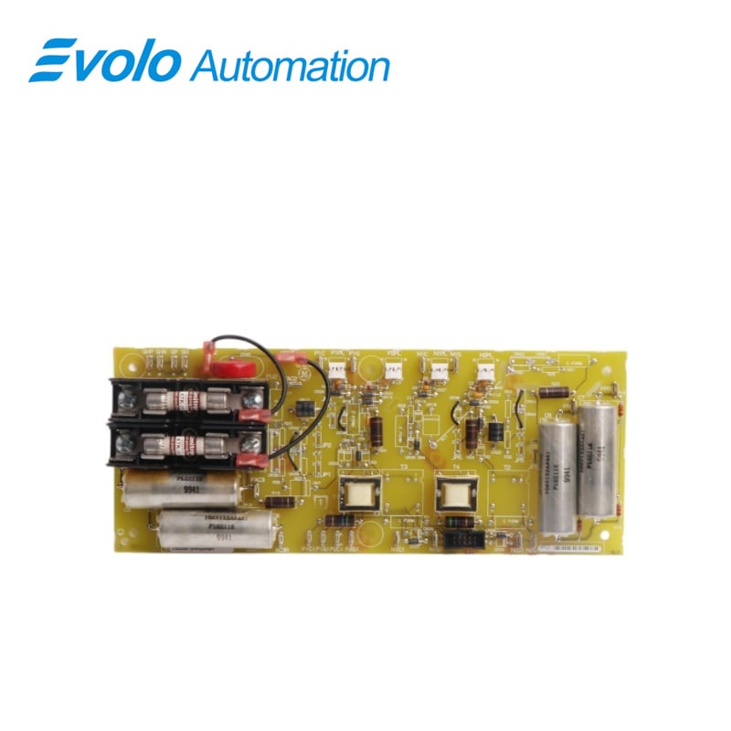
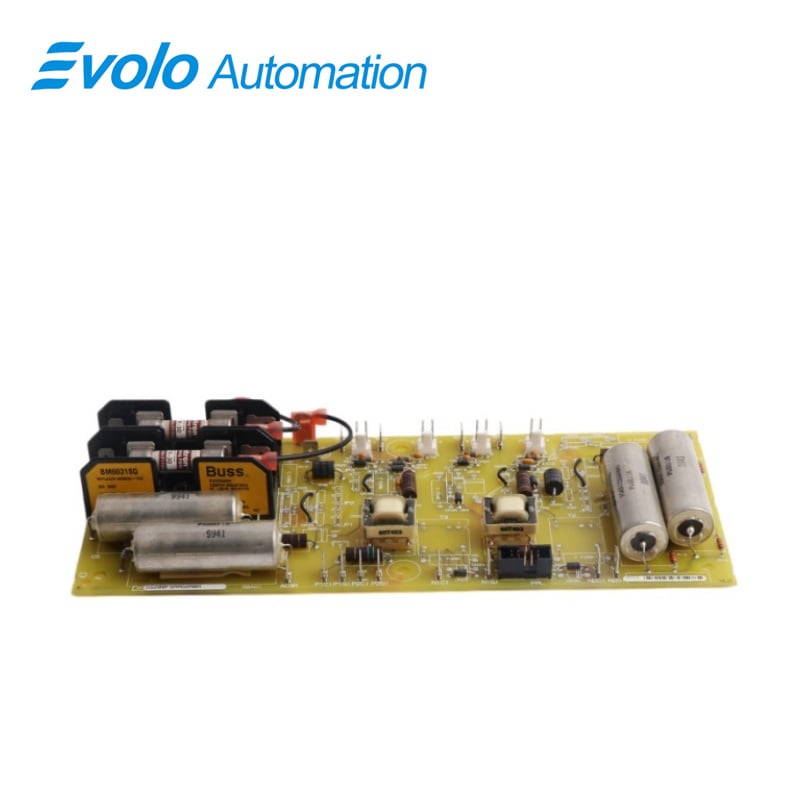
DS200FSAAG2ABA DS2020FECNRX010A is a Field Supply Amplifier Board developed by GE under drive control system. A Field Supply Amplifier Board is a component commonly found in turbine control systems. Its main function is to amplify the low-voltage signal received from the field supply and provide a high-voltage output to the turbine control system. It is typically located near the turbine control system's voltage regulator, where it receives the low-voltage signal. It amplifies the signal to the appropriate level needed by the control system and provides a stable and reliable source of power to the system. It is a type of field exciter that is designed for use in industrial power generation and distribution applications. It has a 24 A NRX capability and makes it an ideal choice for use in demanding industrial environments where high current loads are common. It also features a 10 A shunt, which provides additional protection against electrical overload and other types of damage. This helps to ensure that the device remains reliable and long-lasting, even when used under challenging operating conditions.
Applications
Thermal and Gas Power Plants: Integrated into the GE Mark V control system for managing generator excitation in gas turbines and steam turbines.
Wind Power Plants: Used for automated drive assembly and control of wind turbines.
Nuclear Power Plants: As part of the control system in digital power centers, ensuring stable power conversion.
Heavy Industry and Manufacturing: Large Factory Drive Systems: Used for magnetic field current regulation of large motor drives in automated factories.
Oil and Gas: Drives critical large centrifugal equipment in refineries and pipeline compressor stations.
Features
1.Multiple prong-type connectors are also included on this GE Line Protection Board. The board is mounted on standoffs on another drive component. The signal wires that connect the board to the component to which it is connected begin on the component to which it is attached.
2.The board and the component to which it is connected produce heat and are intended to be connected to a high-voltage current. As a result, the drive must be placed in an atmosphere with enough free-flowing air to keep the drive and its components cool. Once the drive is mounted, you'll observe if it stays cool or if the temperature rises to the point where it reaches the high-temperature threshold and shuts down.
3.First, assess if the drive will be surrounded by other heat-generating equipment and if the components will be too close together. Even if the gadgets generate heat, there is room for the hot air to escape. Fans may be required between the drives and other devices
4.Hoods are sometimes used to gather warm air and vent it out into the surroundings. Make sure the hoods are clean and large enough to do their job. Make sure there is no equipment in surrounding rooms that heat the walls and contributes to the heat around the drive
5.Jumpers and Terminal Blocks: Features 7 jumpers and 2 terminal blocks with 3 terminals each. The jumpers are labeled JP1 through JP7, and they serve as connectors or switches to configure specific settings or connections on the board.The terminal blocks provide a convenient way to connect wires or cables to the board, typically for power or signal purposes.
6.Prong-Type Connectors: Incorporates a number of prong-type connectors. These connectors are designed to establish electrical connections with external devices or components.They usually consist of male and female connectors that fit together securely, ensuring reliable signal or power transmission.
7.Mounting and Standoffs: Mounted on standoffs, which are raised supports that provide spacing between the board and another drive component. This arrangement allows for proper airflow around the board, promoting cooling and preventing heat buildup.The standoffs ensure a secure and stable attachment of the board to the drive component.
Contact and Solenoid Outputs
1.For contact outputs, the Mark V only employs magnetic relays of the plug-in variety (no solid state outputs). Each contact is a three-wire form C with a common center conductor, one generally open and one normally closed contact.
2.In a TMR system, the three controllers R, S, and T each independently decide the contact output state, and the relay driver casts two of the three votes. A diagnostic alarm is announced if there is a disagreement among the three controllers.
3.Depending on the jumper settinas made on the terminal boards, some outputs can be internally powered by either 115 V or 125 V ac. Transformer-mechanical relay contacts are rated out of the box.
Installation and Environmental Considerations
1.Mounting: Install the board on standoffs, securely affixed to another component within the drive system,
2.Signal Wires: Ensure that signal wires connecting to the board originate from the attached component, maintaining a secure and reliable connection.
3.Heat Generation: Both the board and the attached component generate heat due to high-voltage current connections.
4.Cooling Requirement: To prevent overheating, the drive and its components must be placed in an environment with free-flowing air for adequate cooling.
5.Temperature Monitoring: After installation, diligently monitor the drive's temperature. If it approaches a high-temperature threshold, it may automatically shut off to prevent damage.
6.Nearby Devices: Check if surrounding heat-generating devices might affect the drive's temperature. Ensure adequate spacing between components.
7.Ventilation: Create space for heated air to escape. Consider installing fans between drives and other devices to ensure proper ventilation.
8.Fan Functionality: Confirm that any installed fans are capable of moving enough air and are in good working condition to assist in cooling.
9.Hood Usage: Hoods can be employed to collect and exhaust heated air from the environment if necessary to regulate temperature.
10.Hood Maintenance: Regularly clean and maintain hoods to ensure they are appropriately sized and functioning effectively to dissipate heat.
Application software
1.Application software is developed using in-house software automation tools that select and integrate proven GE control and protection algorithms with the I/O sequencing, and displays for each application. Fixed-point data can be processed at a frame rate of 62.5 ms (16 Hz). The frame rate is the amount of time it takes to read control inputs, condition them, run application software, and send output commands to the control valves. While the turbine is running, changes to the application software can be made with password protection and downloaded to the control module.
2.All application software is stored in nonvolatile EEPROM memory in the control module. The application software is executed sequentially and is represented in the form of a ladder diagram. Maintenance personnel can add or change analog loops and sequencing logic using a library of software building blocks. There are alsc math blocks available. The application software documentation, which includes the primary elementary diagram, I/O assignments, and tuning constant settings, is generated directly from the source code and can be printed on-site.
Frequently Asked Questions
Q: What is DS200FSAAG2ABA DS2020FECNRX010A?
A: It is a Field Supply Amplifier Board under the General Electric Drive Control system.
Q: What are the connectors on the GE Line Protection Board for DS200FSAAG2ABA DS2020FECNRX010A?
A: The board includes multiple prong-type connectors that are used to connect it to other drive components and signal wires.
Q: How is the component mounted for DS200FSAAG2ABA DS2020FECNRX010A?
A: It is mounted on standoffs on another drive component.
Q: What is the purpose of the signal wires that connect the board to the component for DS200FSAAG2ABA DS2020FECNRX010A?
A: The signal wires are used to transmit information and commands between the GE Line Protection Board and the component to which it is attached.
Q: Why is it important to ensure that the module stays cool for DS200FSAAG2ABA DS2020FECNRX010A?
A: The GE Drive Control system and its components produce heat and are designed to operate at high voltages. If the temperature inside the drive enclosure rises too high, the system may shut down or suffer damage.