EN
EN




- Overview
- Specifications
- Description
- Applications
- Features
- Connections
- FREQUENTLY ASKED QUESTIONS
- Recommended Products
Overview
Place of Origin: |
USA |
Brand Name: |
GE |
Model Number: |
DS200SDCCG1AGD |
Packaging Details: |
Original new Factory Sealed |
Delivery Time: |
5-7 days |
Payment Terms: |
T/T |
Supply Ability: |
In stock |
Specifications
|
Part Number: |
DS200SDCCG1AGD, DS215SDCCG1AZZ01B |
|
Manufacturer: |
General Electric |
|
Series: |
Mark V |
|
Product Type: |
Drive Control Card |
|
Microcontroller: |
80C196 |
|
Digital Signal Processor: |
TMS320C25 |
|
Software Suite: |
ST2000 |
|
LEDs: |
10 |
|
Dimensions (cm): |
28 x 21.2 x 3 |
|
Weight: |
0.58 kg |
|
Country of Manufacture: |
United States (USA) |
|
Processor: |
Multiple high-performance microprocessors |
|
Interfaces: |
Digital I/O, Analog I/O, Communication interfaces |
|
Materials: |
High-quality insulation and metal, ensures electrical performance and mechanical strength |
|
Operating Temperature: |
-20℃ to +60℃ |
|
Connectors: |
1PL, 2PL, 3PL, 6PL, 7PL, 8PL, 9PL, 11PL for signal transmission and reception |
Description
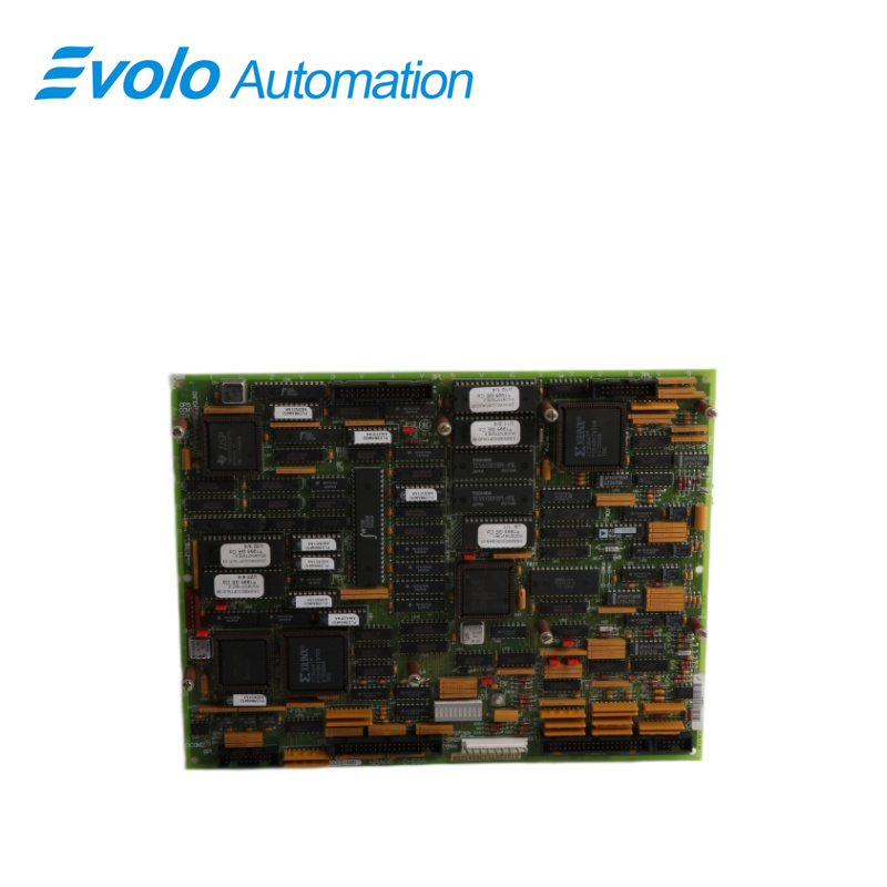
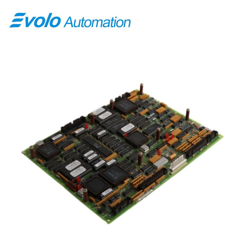
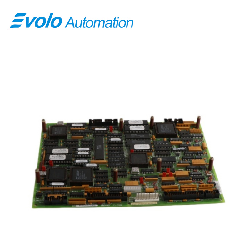
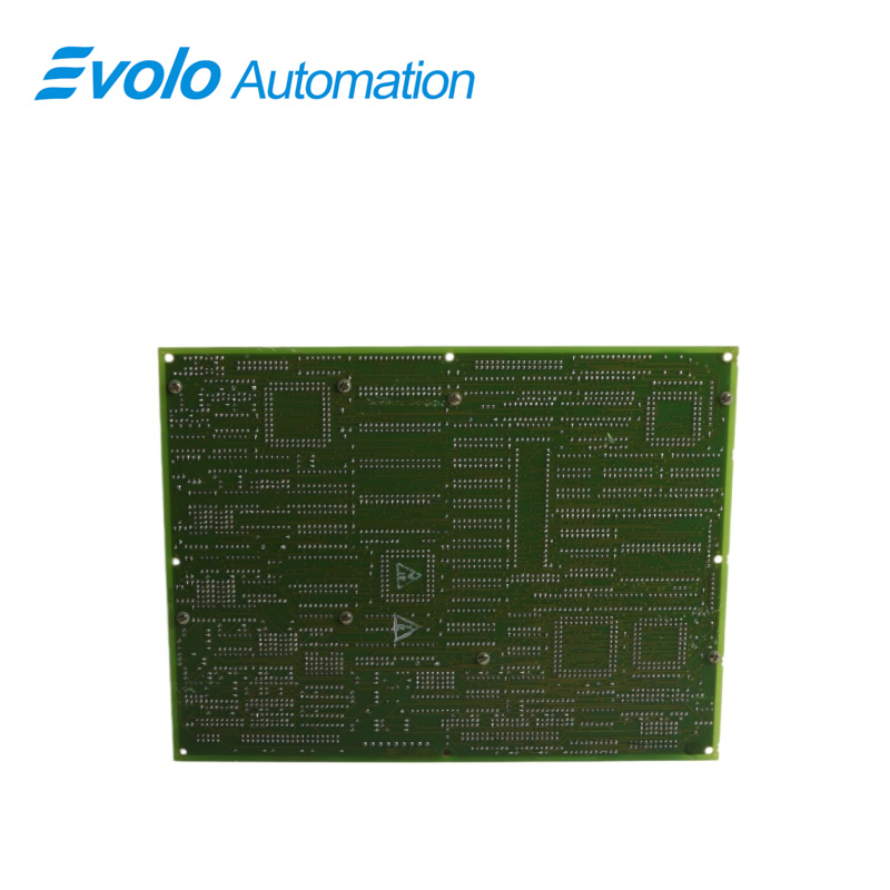
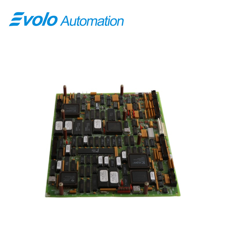
DS200SDCCG1AGD DS215SDCCG1AZZ01B is a Drive Control Card designed and developed by GE.It is a part of Mark V control system.The product contains the primary control circuitry and software for a drive or exciter.It consists of three 16-bit microprocessors and associated circuits coupled via dual-ported RAM.The component also has interface circuitry that joins with other boards to provide various AC and DC motor drive configurations.The interface circuitry regulates, processes and controls drive, motor, and customer I/O signals.The system is completely programmable turbine control system made to handle the complicated, dynamic behavior of steam and gas turbines in the modern power generation industry.It is a modular control system that offers cutting-edge management, supervision, and security.In addition to robust monitoring capabilities and various built-in features that automatically protect the turbine-generator from a range of abnormal operating events, such as overspeed, oil loss, and overheating, this gives operators instant access to all key control operations.
Applications
Power Energy Industry (Core Applications):
Gas Turbine and Steam Turbine Control: Installed in the Mark V control cabinet, responsible for calculating the turbine's start-up, acceleration, synchronization, and load control logic.
Nuclear Power and Large Hydropower: Operates as a core processing unit in power control systems requiring extremely high redundancy and stability.
Oil and Gas:
Large Compressor Drive Stations: Controls gas turbines driving compressors of tens of thousands of horsepower in oil and gas pipelines.
Refineries and Chemical Plants: Manages large rotating machinery used in critical process flows.
Heavy Manufacturing:
Steel Mills and Paper Mills: Integrated into the Directo-Matic 2000 or EX2000 excitation system, precisely controlling the torque and speed of large DC or AC motors.
Features
1.The component is reliable as a control board and serves as the predecessor to the LAN Drive Control Board. Due to its consistent performance and functionality, it is recommended to have a delayed migration when utilizing this board in an application.
2.The module features three main microprocessors: the drive control processor, motor control processor, and co-motor processor. The drive control processor is responsible for controlling the drive and incorporates numerous built-in functions, as well as digital and analog input/output capabilities. It also includes the software for the user interface, allowing for easy interaction with the system. A single microprocessor efficiently handles high-speed input/output, digital input/output, analog input/output, and digital timing functions. The motor control processor is specifically designed to handle math-intensive functions related to motor control.
3.This module is commonly used in AC2000, DC2000, and EX2000 drive applications, showcasing its versatility and compatibility across different drive systems.
4.With a total of eight connectors available, namely 1PL, 2PL, 3PL, 6PL, 7PL, 8PL, 9PL, and 11PL, the module establishes crucial connections for transmitting and receiving signals to and from other boards within the drive system. Each connector serves a specific purpose and facilitates the exchange of data and control signals.
5.When connecting the cables to the module, it is important to ensure that they are routed in such a way that they do not come into contact with other components in the drive, minimizing the risk of interference or damage. To facilitate easy replacement if necessary, it is advisable to label the cables, making it easier to identify their connections and maintain proper organization. Creating these labels while the connector identifiers are readily available simplifies the process and ensures accurate labeling for future reference.
Connections
The Card Connections of the component are essential for establishing communication and connectivity with other boards within the controller system, as well as external signals. These connections are made through eight designated connectors, denoted as "PL." Each connector serves a specific purpose and facilitates the exchange of information and signals between different components.
1PL: This connector enables input and output (I/O) communication between the Power Supply/Interface Board (IMCP, DCI, SDCI, or DCFB) and the SDCC (System Display and Control Card). It allows for the transfer of data and control signals between these two boards.
2PL: The 2PL connector is responsible for connecting various ±5V, 15V, and 24V direct current (DC) inputs from the Power Supply/Interface Board to the component. These inputs provide the necessary power supply voltages to the component for its operation.
3PL: This connector facilitates the transmission of SDCC outputs to the LAN Communications Card (SLCC). It allows for communication between the SDCC and the LAN Communications Card, enabling network connectivity and data exchange.
6PL: The 6PL connector serves as an I/O interface between the Drive Terminal Board (NTB) or Simple Drive Terminal Board and the SDCC. It enables the exchange of control signals, feedback, and other relevant information between these components.
7PL: This connector establishes I/O communication between the Signal Processor Card (SPC) or Multibridge Signal Processing Card and the component. It enables data transfer and signal processing between the component and these signal processing boards.
8PL: Similar to the 6PL connector, the 8PL connector also facilitates I/O communication between the Drive Terminal Board (NTB) or Simple Drive Terminal Board and the SDCC. It provides an additional interface for data exchange and control signals.
9PL: The 9PL connector is labeled as "Not Used," indicating that it does not have a designated function or connection in this configuration or context.
11PL: This connector is responsible for the outputs to meters. It allows for the connection of metering devices or instruments, enabling the display and monitoring of relevant parameters or measurements.
FREQUENTLY ASKED QUESTIONS
Q: What is DS200SDCCG1AGD DS215SDCCG1AZZ01B?
A: It is a Drive Control Card developed by General Electric.
Q: How many microprocessors are there on the DS200SDCCG1AGD DS215SDCCG1AZZ01B?
A: There are three 16-bit microprocessors on the SDCC, along with associated circuits coupled via dual-ported RAM.
Q: What is the function of the interface circuitry?
A: The interface circuitry on the SDCC regulates, processes, and controls drive, motor, and customer I/O signals. It works with other boards to provide various AC and DC motor drive configurations.
Q: What is the ST2000 software suite of DS200SDCCG1AGD DS215SDCCG1AZZ01B?
A: The ST2000 software suite is a DOS-based package used to configure GE DIRECTO-MATIC 2000 control equipment. It is used to configure and monitor the control equipment and can perform functions such as diagnostics, tuning, and calibration.
Q: What is the GE Control System Toolbox of DS200SDCCG1AGD DS215SDCCG1AZZ01B?
A: The GE Control System Toolbox is a set of software tools used to configure GE DIRECTO-MATIC 2000 control equipment. It runs on Windows and is used for configuring hardware and software parameters, editing ladder logic programs, and monitoring real-time data.
Q: What is the LynxOS Drive Configurator of DS200SDCCG1AGD DS215SDCCG1AZZ01B?
A: The LynxOS Drive Configurator is a software suite used to configure GE DIRECTO-MATIC 2000 control equipment on a PC running the LynxOS operating system. It provides a graphical interface for configuring and monitoring the control equipment.