EN
EN




- Overview
- Specifications
- Description
- Applications
- DRIVE CONTROL PROCESSOR(DCP)
- CONNECTIONS
- FREQUENTLY ASKED QUESTIONS
- Recommended Products
Overview
Place of Origin: |
USA |
Brand Name: |
GE |
Model Number: |
DS200SDCCG1A |
Packaging Details: |
Original new Factory Sealed |
Delivery Time: |
5-7 days |
Payment Terms: |
T/T |
Supply Ability: |
In stock |
Specifications
|
Part Number: |
DS200SDCCG1A |
|
Manufacturer: |
General Electric |
|
Function: |
Drive Control Card |
|
Series: |
Mark V |
|
Operating Temperature: |
-30 to 65°C |
|
Dimensions (cm): |
28.8 x 7.2 x 3.7 |
|
Weight: |
0.38 kg |
|
Country of Origin: |
USA |
|
External RAM: |
Two dual-ported RAMs for increased processing power |
|
Memory Chips: |
1 EEPROM (U9) for field-adjustable settings, 4 EPROMs (U11, U12, U22, U23) with factory-programmed configuration data |
|
Microprocessors: |
Three 16-bit dual-ported RAM-connected microprocessors |
|
Voltage: |
12V DC |
Description
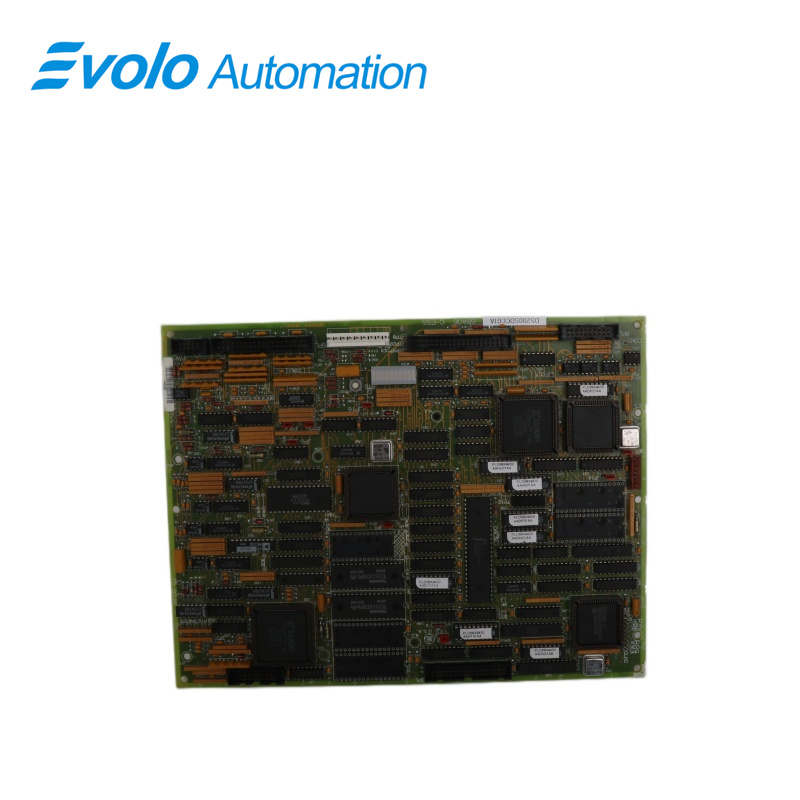
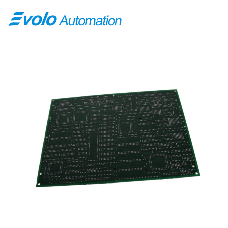
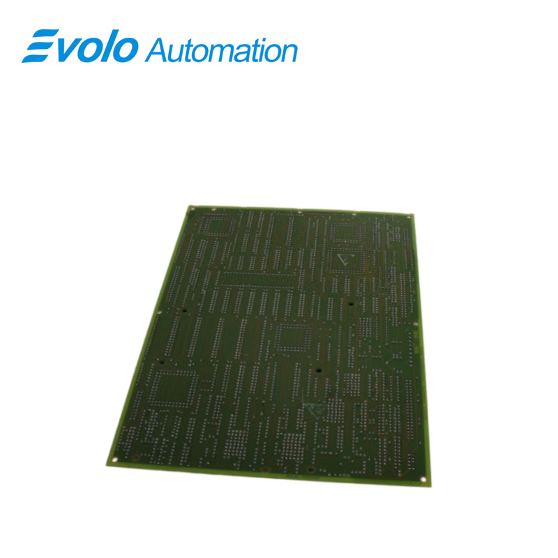
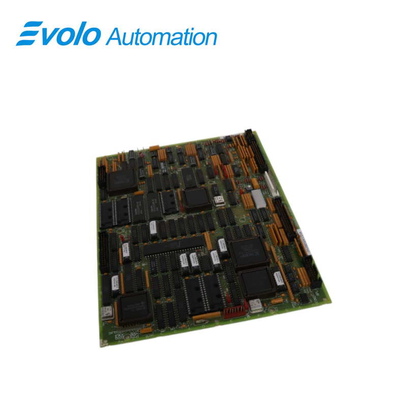
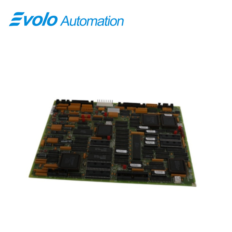
DS200SDCCG1A is a Drive Control Card manufactured and designed by General Electric as part of the Mark V series used in Speedtronic Control Systems.The Drive Control Card (SDCC), the main processor board, houses the electronics that control the EX2000 primarily.It comprises three dual-ported RAM-connected 16-bit microprocessors with related circuitry.It incorporates general-purpose interface circuitry that may be connected to other circuit boards to create different kinds of excitation systems.This interface circuitry manages the exciter and customer I/O.Two external dual-ported RAMs are also used to increase processing power.The SDCC also has interface circuitry that joins with other boards to provide various AC and DC motor drive configurations.The interface circuitry regulates, processes, and controls drive, motor, and customer I/O signals.(In TC2000 applications, extra tasks are performed using the three primary microprocessors and the interface circuitry.)
Applications
Power Industry:
Turbine Control: Installed in the GE Mark V control cabinet, directly manages the operating logic of the gas turbine or steam turbine (e.g., startup, synchronization, loading).
Excitation System: Calculates the magnetic field current demand within the generator excitation cabinet and sends trigger pulses to the power bridge.
Heavy Industrial Drives:
Large Motor Control: As the core of the Directo-Matic 2000 drive, used to control large AC/DC motors in steel mills, paper mills, or mines.
Signal Coordination: Receives feedback from tachometers, temperature sensors, and pressure transmitters, and adjusts the drive output in real time.
DRIVE CONTROL PROCESSOR(DCP)
An 80C186 microcontroller (U1) uses both digital and analog I/O and has many built-in peripheral features.These features include the direct memory access (DMA) controller, timers/counters, an interrupt controller, wait-state generators, and address decoding for chip selects.User interfaces, external regulating loops (such as speed and location), and system-level operations make up DCP software.
1.Motor Control Processor (MCP): A microcontroller (U21) based on the 80C196 featuring high-speed, conventional, analog, and digital I/O as well as timer/counters and a watchdog timer. MCP software includes motor/technology-specific operations like dc phase control, ac motion control, and ac general purpose, as well as inner loops like current regulators.
2.Co-motor Processor (CMP): For motor control algorithms that are too sophisticated for the MCP, a TMS32002 signal processor (U35) conducts math-intensive operations. Only when the drive requires the extra processing power does the SDCC use this processor and the electronics that goes along with it. Only its EPROM and MCP/CMP dual-ported RAM are exposed to the CMP interface.
3.Five memory chips make up the onboard software for the DS215SDCC card: one EEPROM (U9) holds field-adjustable settings, and four EPROMs (U11, U12, U22, and U23) have factory-programmed configuration data. Located in sockets on the SDCC are these memory chips.
CONNECTIONS
Eight connectors (marked _PL) connect the SDCC to the other controller boards and external signals. The positions of the connections are depicted in Figure 3 along with tables 3 through 9 that list the pin signals for each connector. The following are connectors to other boards:
1.The Power Supply/Interface Board's 2PL inputs at 5, 15, and 24 V dc are connected to the SDCC. The LAN Communications Card receives outputs from the 3PL SDCC(DS215SLCC)
2.6PL I/O between the SDCC and the Simple Drive Terminal Board (DS200STBA) or Drive Terminal Boar (531X305NTB).
3.7PLI/O between the SDCC and the Multibridge Signal Processing Card (DS200SPCB) or Signal Processor Card (531X309SPC)(not present on SDCCG3s)
4.8PL I/O between the SDCC and the Simple Drive Terminal Board (DS200STBA) or Drive Terminal Boar (531X305NTB).
5.9PL-Not Used:(not present on SDCCG3s) SDCC outputs to 11PL meters (not present on SDCCG3s)
FREQUENTLY ASKED QUESTIONS
Q: What is a DS200SDCCG1A Drive Control Card?
A: A Drive Control Card is an essential component in turbine and motor control systems, designed to regulate drive configurations, motor operations, and customer I/O signals. It plays a critical role in managing excitation systems and motor drives in industrial applications.
Q: What does the DS200SDCCG1A Drive Control Card control?
A: The Drive Control Card manages various systems, including excitation systems, AC and DC motor drives, and customer input and output signals. Its functionality extends to controlling system-level operations and coordinating drive and motor configurations effectively.
Q: What processors are on the DS200SDCCG1A Drive Control Card?
A: The card is equipped with three processors: the Drive Control Processor (DCP), the Motor Control Processor (MCP), and the Co-Motor Processor (CMP). The DCP handles system-level operations and external regulating loops, the MCP manages motor-specific tasks like AC/DC control and current regulation, and the CMP performs advanced calculations for complex motor control algorithms.