EN
EN




- Overview
- Specifications
- Description
- Applications
- Special Handling
- Physical Installation
- FAQ
- Recommended Products
Overview
Place of Origin: |
Sweden |
Brand Name: |
ABB |
Model Number: |
IMDSI22 |
Packaging Details: |
Original new Factory Sealed |
Delivery Time: |
5-7 days |
Payment Terms: |
T/T |
Supply Ability: |
In stock |
Specifications
|
Parameter |
Value |
|
Model |
IMDSI22 |
|
Description |
INFI 90 Digital Input Module |
|
Dimension |
3.7x31.7x17.8 cm |
|
Weight |
0.22 kg |
|
Digital Input Voltage |
24 VDC, 48 VDC, 125 VDC, 120 VAC |
|
Power Requirements |
Operating current: 95 mA at 5 VDC typical; 115 mA maximum |
|
Overvoltage Category |
ANSI/ISA S82.01-1994 & IEC 61010-1: I for power, I for circuits >150 V, II for circuits <150 V |
|
Operating Temperature |
0° to 70°C (32° to 158°F) (cabinet internal rating) |
|
Relative Humidity |
5% to 95% up to 55°C; 5% to 45% at 70°C (non-condensing) |
|
Pollution Degree |
1 |
|
Atmospheric Pressure |
Sea level to 3 km (1.86 miles) |
|
Electrostatic Discharge (IEC 1000-4-2, EN 61000-4-2) |
Contact: ±6 kV; Air: ±8 kV |
|
Power Frequency Magnetic Field |
Continuous: 30 A/m (rms); Short duration: 300 A/m (rms) |
|
Pulse Magnetic Field |
Peak value: 300 A/m |
|
Damped Oscillatory Magnetic Field (0.1–1 MHz) |
Peak value: 30 A/m |
|
Radiated RF Electromagnetic Field (80 MHz–1 GHz) |
Unmodulated rms: 10 V/m; Amplitude modulated 80% AM (1 kHz) |
|
Radiated RF Field (900 ±5 MHz) |
Unmodulated rms: 10 V/m; Pulse modulated: Duty cycle 50%, Rep. cycle 200 Hz |
|
Radio-Frequency Common Mode (0.15–80 MHz) |
Unmodulated rms: 10 V/rms; Amplitude modulated 80% AM (1 kHz); Source impedance: 150 Ω |
Description
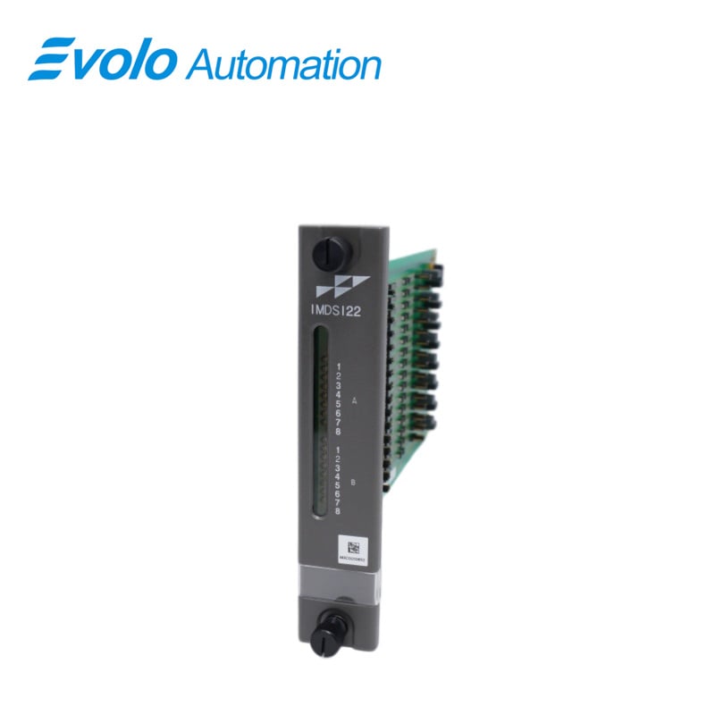
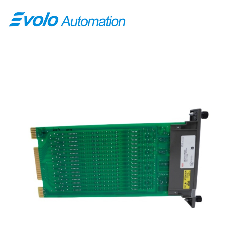
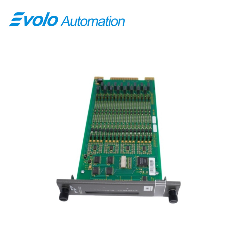
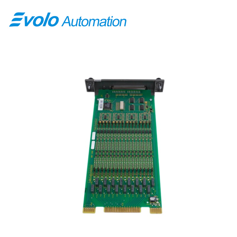
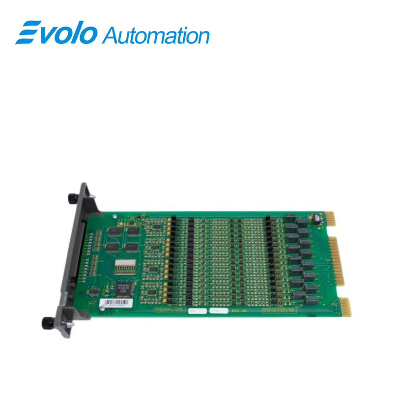
The IMDSI22 digital input module consists of a single printed circuit board that occupies one slot in a module mounting unit. It monitors two separate groups of eight digital inputs. Twelve inputs are isolated from each other; the remaining two pairs share common positive input lines. Two captive screws on the module faceplate secure it to the module mounting unit. Sixteen front panel LED status indicators (group A and group B) display the input status and provide aid in system test and diagnosis. The digital input module has three card edge connectors for external signals and power (P1, P2 and P3). P1 connects to common (ground) and +5 VDC power. P2 connects the module to the I/O expander bus to communicate with a controller. P3 inputs the digital signals using a cable connected to a termination unit. The terminal blocks (physical connection points) for field wiring are on the termination unit.
Applications
Power and Energy Plants:
Thermal Power Plants: Used for monitoring boiler interlock status, turbine auxiliary equipment status, and circuit breaker position feedback.
Renewable Energy: Operates in remote management and SCADA systems for large solar or wind power networks.
Oil, Petrochemical, and Gas Industries: Used for valve open/close feedback, level switch monitoring, and Safety Instrumented Systems (SIS) integration in refineries, oil and gas processing plants, and offshore platforms.
Pulp and Paper Mills: Monitors paper machine status, pulp delivery pump operation, and limit switches on complex continuous production lines.
Mining and Metallurgical Plants: Used for sintering and blast furnace control in steel plants, and conveyor belt monitoring and material handling systems in mineral processing plants.
Chemical and Pharmaceutical Plants: Ensures safe monitoring of reactor status and precise logic control for batch processing in fine chemical and pharmaceutical plants.
Water Treatment and Environmental Protection Facilities: Used for monitoring pump stations and filter status in wastewater treatment plants and water supply networks.
Special Handling
1. Use Static Shielding Bag. Keep the module in its static shielding bag until you are ready to install it in the system. Save the bag for future use.
2. Ground Bags before Opening. Before opening a bag containing an assembly with static sensitive devices, touch it to the equipment housing or ground to equalize charges.
3. Avoid Touching Circuitry. Handle assemblies by the edges; avoid touching the circuitry.
4. Avoid Partial Connection of Static Sensitive Devices. Verify that all devices connected to the modules are properly grounded before using them.
5. Ground Test Equipment.
6. Use an Antistatic Field Service Vacuum. Remove dust from the cards if necessary.
7. Use a Grounded Wrist Strap. Connect the wrist strap to the appropriate grounding plug.
8. Do Not Use Lead Pencils to Set Dipswitches. To avoid contamination of switch contacts that can result in unnecessary circuit board malfunction, do not use a lead pencil to set a dipswitch.
Physical Installation
1. Verify the slot assignment of the module.
2. Verify that a dipshunt is in the I/O expander bus socket on the module mounting unit backplane between the I/O module and controller.
3. For termination units, connect the hooded end of the termination cable from the termination unit to the module mounting unit backplane. To do this, insert the connector into the backplane slot in the same slot as the one assigned to the DSI module. The latches should snap securely into place.
4. Align the DSI module with the guide rails in the module
mounting unit. Gently slide the module in until the front panel is flush with the top and bottom of the module mounting unit frame and the module is seated in the cable to the termination unit.
5. Push and turn the two captive retaining screws on the module faceplate one half turn to the latched position. It is latched when the slots on the screws are vertical and the open ends face the center of the module.
FAQ
Q: What is the IMDSI22?
A: It is a Bailey Infi 90 Digital Input Module.
Q: What about your delivery time of IMDSI22?
A: Generally 1-3 days after receiving your payment. The specific delivery time depends on the type and quantity of the order.
Q: How long is the warranty period of IMDSI22?
A: We offer a standard one-year warranty for all new and original products.
Q: Do you offer any discounts?
A: Yes! For discounts on IMDSI22, please contact John for the best offer.