EN
EN




- Overview
- Specifications
- Description
- Applications
- BENEFITS
- FREQUENTLY ASKED QUESTIONS
- Recommended Products
Overview
Place of Origin: |
USA |
Brand Name: |
GE |
Model Number: |
DS200PCCAG9ACB |
Packaging Details: |
Original new Factory Sealed |
Delivery Time: |
5-7 days |
Payment Terms: |
T/T |
Supply Ability: |
In stock |
Specifications
|
Part Number: |
DS200PCCAG9ACB |
|
Manufacturer: |
General Electric |
|
Series: |
EX2000 |
|
Product Type: |
Power Connect Card |
|
Power Requirements: |
+5 V dc, 6 A |
|
Number of Relay Channels: |
12 |
|
Power Supply Voltage: |
28 V dc |
|
Technology: |
Surface mount |
|
Operating Temperature: |
-30 to +65°C |
|
Dimensions: |
28x21.4x2.3 cm |
|
Weight: |
0.4 kg |
|
Country of Origin: |
United States |
|
Signal Path: |
Sent to PCCA through SPL |
|
Armature Voltage: |
240-630 Volts |
|
Scaling Group: |
G9, Regenerative |
Description
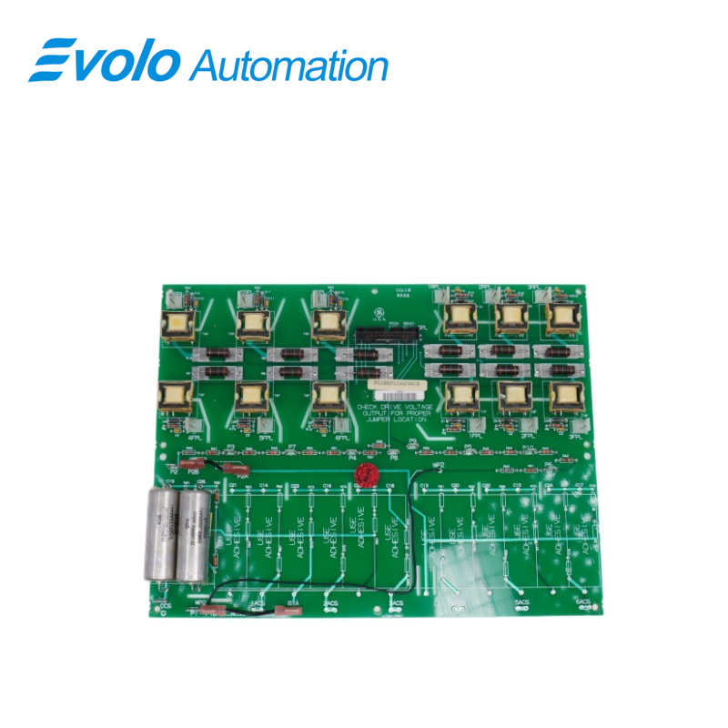
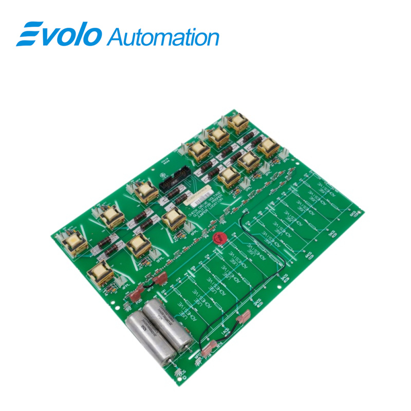
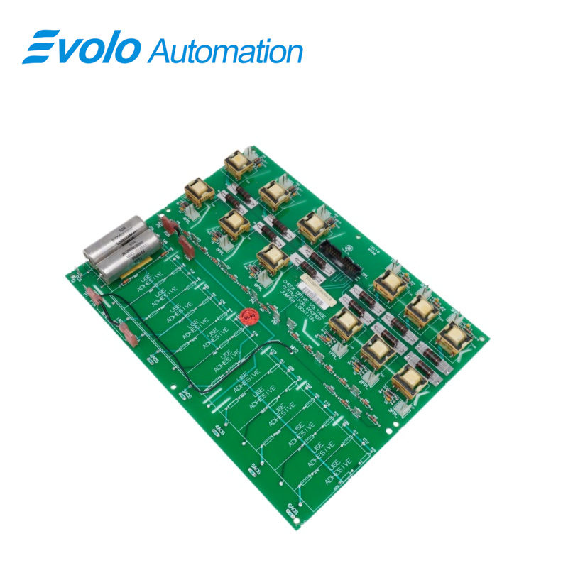
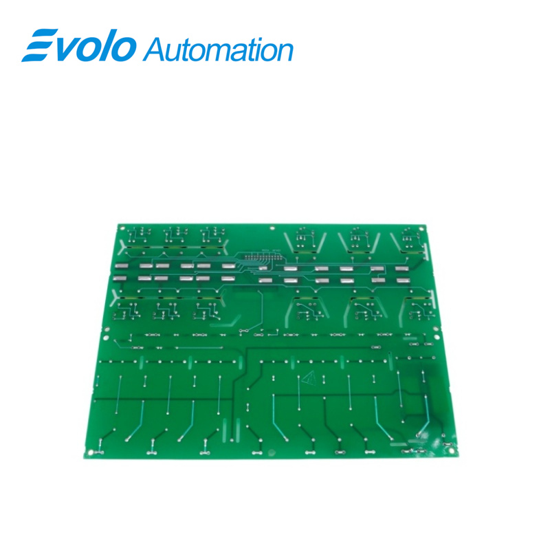
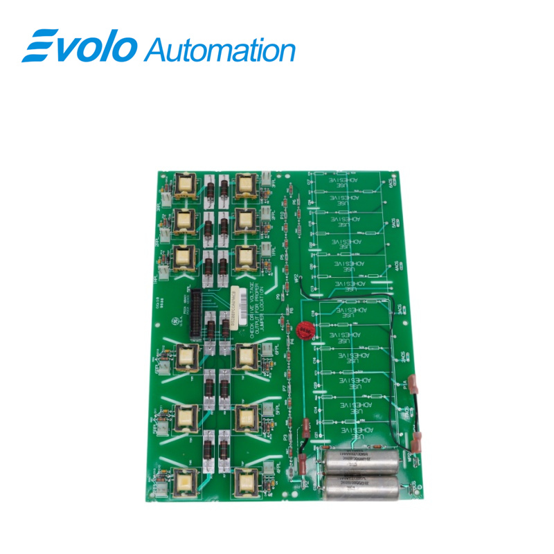
DS200PCCAG9ACB is a Power Connect Card manufactured and designed by General Electric as part of the EX2000 Series used in GE Excitation Control Systems. The Power Connect Card (PCCA) provides an interface between the drive's control circuitry and the SCR power bridge. The PCCA board uses pulse transformers to provide a gate drive to the SCR bridge. For low-to-medium horsepower controllers, the PCCA board also includes snubber circuits to control spikes across the AC lines, DC bus, and gate drivers. For higher horsepower controllers, some or all of the snubber circuits are omitted from the PCCA board and are located elsewhere in the system. The PCCA board has ten group numbers. The group number used in a system is determined by the system voltage, frame size, and whether the system uses regenerative or non-regenerative power conversion.
Applications
Power Industry (Core Applications):
Gas/Steam Turbine Units: Installed in Mark V control cabinets, converting and distributing externally input power (typically 125V DC or 115/230V AC) to the core logic board of the control system (such as the LDCC control board).
Excitation System: Located in the generator excitation cabinet, serving as an interface board connecting power cables to support a stable delivery of excitation current.
Heavy Industrial Drives:
Steel and Paper Mills: Integrated into the Directo-Matic 2000 drive for managing the power distribution of large electric motors.
Oil and Gas Transportation: In the drive control of large compressors in booster stations, ensuring the control circuitry is unaffected by grid fluctuations.
BENEFITS
The 5 V outputs of the gate array are converted by gate pulse amplifier circuits into the power level required to feed the forward and reverse gate pulse transformers on the PCCA card. These signals are sent to the PCCA through SPL. To prevent spurious firing signals, the firing power is removed from the gating circuits until the gate array is programmed and the 5 V power is regulated. The PCCA uses pulse transformers to provide a gate drive to the SCR bridge. For low-to-medium horsepower controllers, the PCCA also includes snubber circuits to control spikes across the AC lines, DC bus, and gate drivers. For higher horsepower controllers, some or all of the snubber circuits are omitted from the PCCA and are located elsewhere in the system.
FREQUENTLY ASKED QUESTIONS
Q: What is the purpose of the snubber circuits on the DS200PCCAG9ACB PCCA board?
A: Snubber circuits are used to suppress voltage spikes and transients that can occur across the AC lines, DC bus, and gate drivers. They help protect the system from damage and ensure smooth operation, particularly in low-to-medium horsepower controllers.
Q: Why are snubber circuits omitted in higher horsepower controllers of DS200PCCAG9ACB?
A: In higher horsepower controllers, the power requirements are more demanding, and snubber circuits are typically located elsewhere in the system, rather than on the PCCA board, to optimize performance and manage heat dissipation more efficiently.
Q: How do I determine the correct stab terminals for jumpers JP1 and JP2 of DS200PCCAG9ACB?
A: The correct stab terminals for jumpers JP1 and JP2 are based on the card group number and system voltage. These parameters must be considered to ensure proper connections and functionality within the system.