EN
EN




- Overview
- Quick Detail
- Description
- Generator Voltage and Current Measurement Configurations
- Voltage Test Points and Important Considerations
- Application Data
- Frequently Asked Questions
- Recommended Products
Overview
Place of Origin: |
USA |
Brand Name: |
GE |
Model Number: |
IS200EPCTG1AAA |
Packaging Details: |
Original new Factory Sealed |
Delivery Time: |
5-7 days |
Payment Terms: |
T/T |
Supply Ability: |
In stock |
Quick Detail
|
Part Number: |
IS200EPCTG1AAA |
|
Manufacturer: |
General Electric |
|
Country of Manufacture: |
USA |
|
Product Type: |
Exciter PT/CT (EPCT) terminal board |
|
Series: |
EX2100 |
|
Number of Channels: |
6 |
|
Dimensions: |
33x11.3x3.5 cm |
|
Weight: |
0.86 kg |
|
Operating Temperature: |
-30 to 65 °C |
|
PT Inputs: |
Two 3-phase generator potential transformer inputs, 115 V rms, 50/60 Hz, fused |
|
CT Inputs: |
Two generator current transformer inputs, 0-1 A or 0-5 A options |
|
Analog Input: |
Single analog input, accepts voltage or current |
|
Isolation Transformers: |
Two voltage isolation transformers for 3-wire open delta measurement |
|
Terminal Blocks: |
TB1 removable, TB2 and TB3 fixed |
|
Voltage Test Points: |
TP1-TP8 on secondary side of isolation transformers |
|
Sub-D Connectors: |
J305, J308, J315 for EMIO board connections |
|
Maximum Cable Length: |
PT up to 1000 ft (12 AWG), CT up to 1000 ft (#10 AWG) |
|
Redundancy: |
Supports up to three EPCT boards for redundant control |
Description
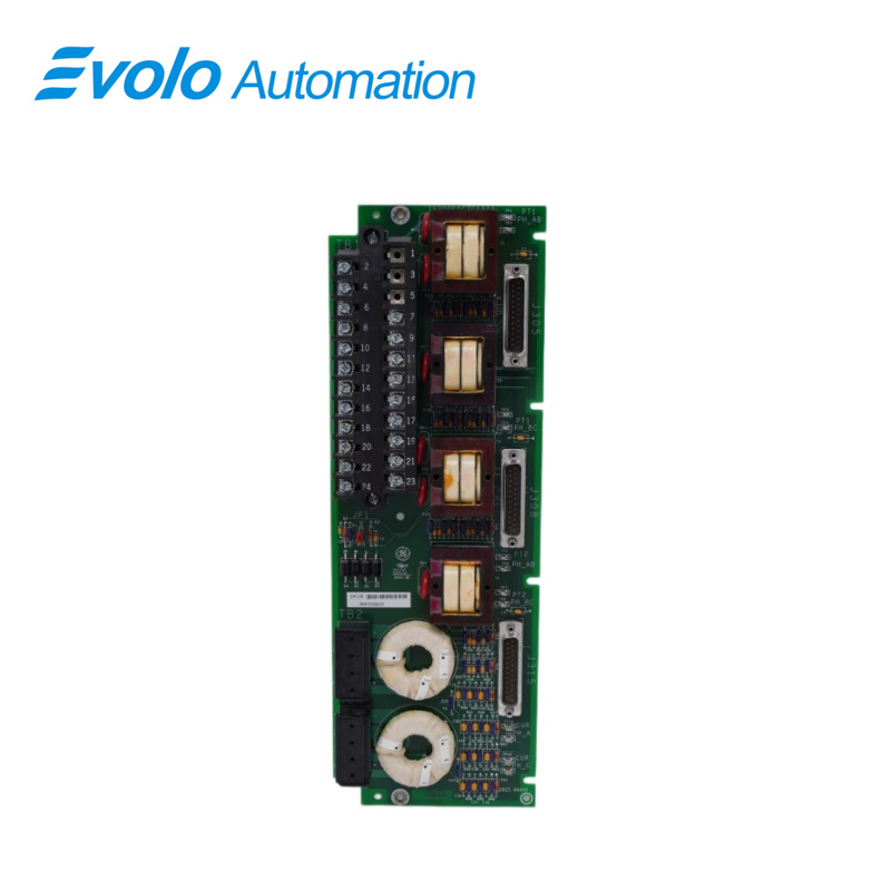
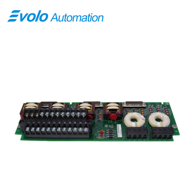
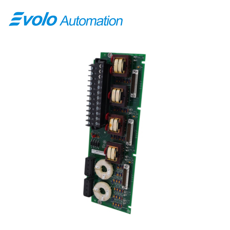
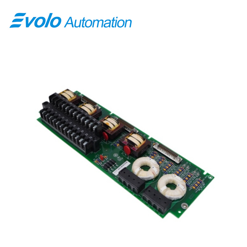
IS200EPCTG1AAA is an Exciter PT/CT (EPCT) terminal board developed by GE. It is a part of EX2100 excitation system. Exciter PT/CT (EPCT) terminal board serves as an indispensable component specifically designed to handle critical measurements of generator voltage and current via isolation transformers. This board integrates two 3-phase generator potential transformer (PT) voltage inputs and two generator current transformer (CT) inputs, offering current options of 1 A or 5 A. All output signals from the isolation transformers are efficiently cabled to the EMIO board, strategically positioned within the control rack. Additionally, EPCT accommodates a single analog input, capable of accepting either voltage or current inputs. For applications demanding the utmost reliability, the system can incorporate up to three EPCT boards, ensuring redundancy and system robustness.
Generator Voltage and Current Measurement Configurations
The board's functionality involves receiving generator voltages from the customer's potential transformers, directing these inputs through switches to TB1. This setup allows for cable lengths of up to 1000 ft using 12 AWG wire.The PT inputs, typically operating at a nominal 115 V rms and 50/60 Hz frequency, are fused to ensure protection against potential electrical anomalies.
Within the board, two isolation transformers effectively execute a three-wire open delta voltage measurement, generating an output of 1.533 V rms from a 115 V rms input. Regarding the CT inputs, two generator current inputs from the CTs are connected to non-pluggable terminal blocks, TB2 and TB3. Each current transformer features a 0-1 A rms winding and a 0-5 A rms winding, with only one wired to EPCT. The cable length from the transformer to the board can extend up to 1000 ft, accommodating wire gauges of up to # 10 AWG for reliable transmission.
Voltage Test Points and Important Considerations
Incorporates four voltage test points (Tp9-12), strategically positioned on each leg of the secondary side of the generator current isolation transformers. It is crucia
to note that these test points should not be grounded through the measuring device
This design decision is essential to ensure accurate measurements and prevent potential interference that could compromise the measurement accuracy.
Application Data
The board's layout, as depicted in the Board Layout, showcases the arrangement of components. T1 through T6 denote the voltage and current isolation transformers, essential for their respective measurements. Terminal block TB1, held in place by two screws, is designed for removal if necessary. However, terminal blocks TB2 and TB3 are intentionally fixed, serving as a protective measure against a potential CT open circuit situation
In a simplex control setup, the voltage signals are directed through the J305 connector to the EMlIO board situated in the M1 controller. Conversely, in a redundant control configuration, these signals are distributed, allowing connection to connectors J305,J308, and J315.Subsequently, they are transmitted to controllers M1, M2, and C, ensuring redundancy and system resilience
Facilitates measurements through eight voltage test points (TP1-8), strategically located on each leg of the secondary side of the isolation transformers. These test points offer convenient access for diagnostic and testing purposes
The system incorporates three 25-pin sub-D connectors, namely J305, J308, and J315. These connectors are designated for cable connections to the EBKP backplane, enabling seamless linkage to the EMlO board, thus facilitating communication and data transfer within the system configuration.
Frequently Asked Questions
What is IS200EPCTG1AAA?
It is an Exciter PT/CT (EPCT) terminal board developed by GE under the EX2100 series
What is the primary function of the IS200EPCTG1AAA Exciter PT/CT (EPCT) terminal board?
The board is designed to handle critical measurements of generator voltage and current through its integrated isolation transformers.
What are the primary inputs supported by the IS200EPCTG1AAA terminal board?
The board accommodates two 3-phase generator potential transformer (PT) voltage inputs and two generator current transformer (CT) inputs, available with current levels of either 1 A or 5 A
How are the isolation transformer output signals managed of IS200EPCTG1AAA?
All signals from the isolation transformers within the EPCcT board are efficiently cabled to the EMlO board situated in the control rack for further processing and manaqement.