EN
EN




- Overview
- Specifications
- Description
- Applications
- Physical Installation
- Troubleshooting
- FAQ
- Recommended Products
Overview
Place of Origin: |
Sweden |
Brand Name: |
ABB |
Model Number: |
SPDSI13 |
Packaging Details: |
Original new Factory Sealed |
Delivery Time: |
5-7 days |
Payment Terms: |
T/T |
Supply Ability: |
In stock |
Specifications
|
Model: |
SPDSI13 |
|
Type |
Digital Input Module |
|
Dimensions: |
3.5 x 31.5 x 17.6 cm |
|
Weight: |
0.2 kg |
|
Operating Voltage: |
24 V DC |
|
Operating Current: |
95 mA typical at 5 VDC, 115 mA maximum |
|
Turn-on Voltage (min): |
19.5 V DC |
|
Turn-off Voltage (max): |
13 V DC |
|
Maximum Input Current: |
4 mA at minimum turn-on voltage |
|
Off-leakage Current: |
50 nA (at Vin ≤ 0.5 VDC) |
|
Over Voltage Category: |
I for power, I for circuits >150 V, II for circuits <150 V (ANSI/ISA82.01-1994 & IEC 61010-1) |
|
Electrostatic Discharge: |
Contact ±6 kV, Air ±8 kV (IEC 61000-4-2, EN61000-4-2) |
|
Power Frequency Magnetic Field: |
Continuous 30 A/m (rms), Short duration 300 A/m (rms) (IEC 61000-4-8, EN61000-4-8) |
|
Pulse Magnetic Field: |
Peak value 300 A/m (IEC 61000-4-9, EN61000-4-9) |
|
Damped Oscillatory Magnetic Field: |
Peak value 30 A/m, 0.1–1 MHz (IEC 61000-4-10, EN 61000-4-10) |
|
Radiated RF Electromagnetic Field: |
Unmodulated rms 10 V/m, Amplitude modulated 80% AM (1 kHz), 80 MHz–1 GHz (IEC 61000-4-3) |
|
Ambient Temperature: |
0° to 70°C (32° to 158°F) internal cabinet rating |
|
Relative Humidity: |
5% to 95% up to 55°C (131°F), non-condensing |
|
Relative Humidity at 70°C: |
5% to 45%, non-condensing |
|
Pollution Degree: |
1 |
|
Atmospheric Pressure: |
Sea level to 3 km (1.86 miles) |
|
Air Quality: |
Non-corrosive (per ISA S71.04, Class LA, LB, LC-level1) |
Description
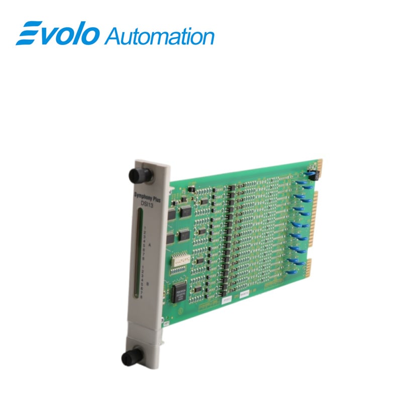
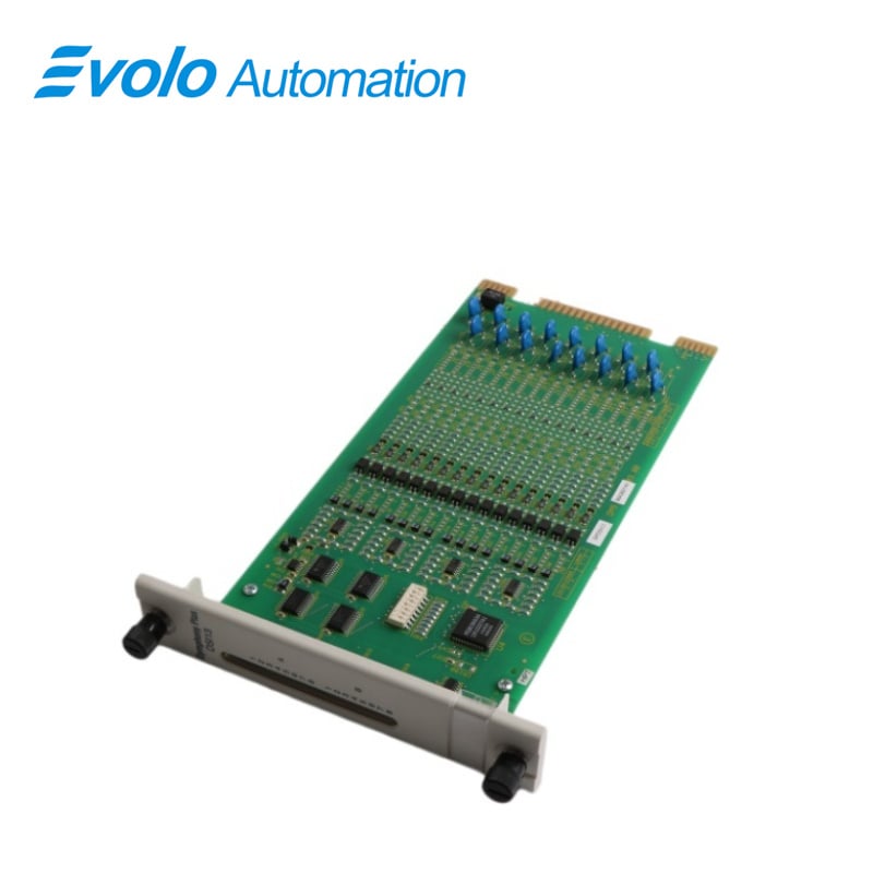
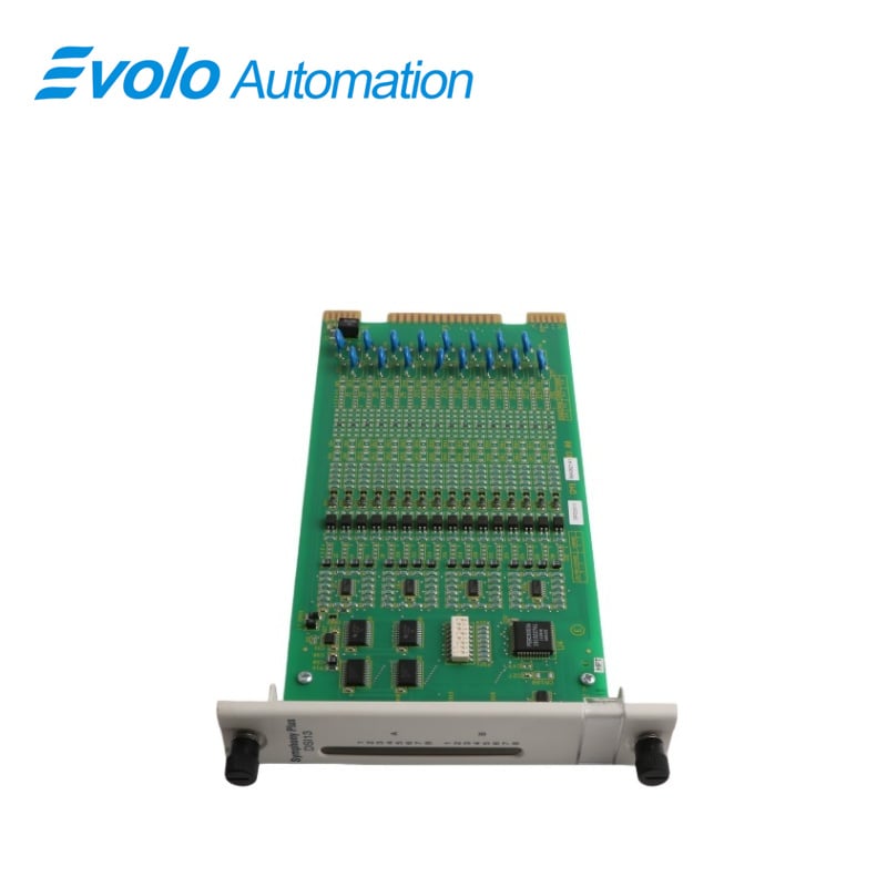
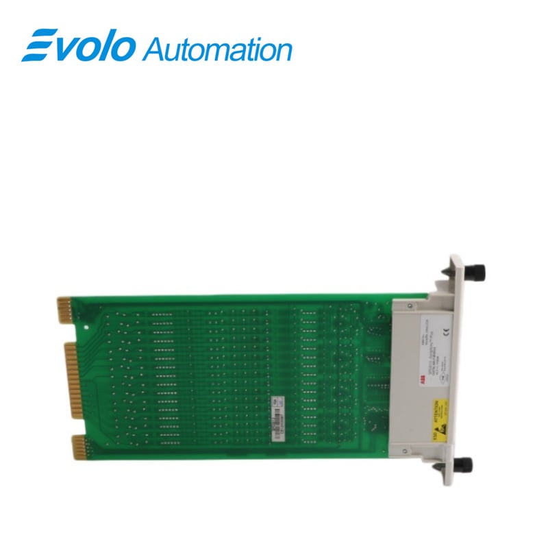
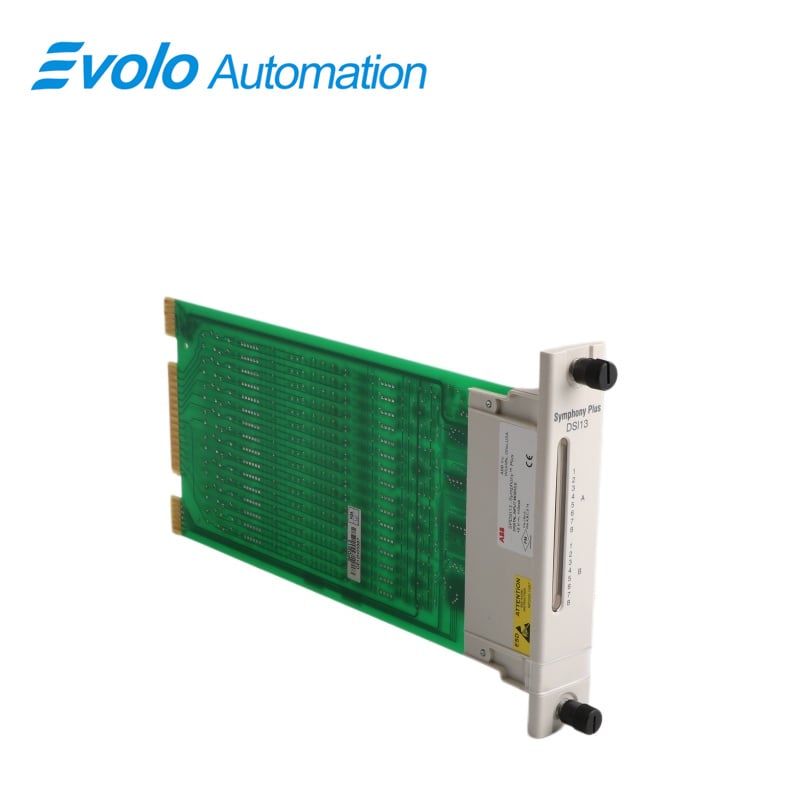
The SPDSI13 Digital Input Modules are interfaces used to bring 16 separate process field signals into the Symphony Enterprise Management and Control System. These digital inputs are used by the controller to monitor and control a process. The digital input module consists of a single printed circuit board that occupies one slot in a module mounting unit. It monitors two separate groups of eight digital inputs. Twelve inputs are isolated from each other; the remaining two pairs share common positive input lines.
Applications
Thermal power plants: Monitoring auxiliary unit interlock switches, valve travel limit switches, and circuit breaker status.
Chemical plants: Acquiring reactor level switch signals and emergency stop button status.
Water treatment plants: Monitoring pump start/stop feedback and filter differential pressure alarm signals.
Paper mills: Inputting conveyor belt misalignment switch and paper roll position detection sensor signals.
Steel plants: Acquiring data for blast furnace material level control and cooling system flow control switches.
Physical Installation
1.Verify the slot assignment of the module. Disconnect power before installing dipshunts on the module mounting unit backplane. Failure to do so will result in contact with cabinet areas that could cause severe or fatal shock.
2. Verify that a dipshunt is in the l/O expander bus socket on the module mounting unit backplane between the l/O module and controller.
3.For terminaton units, connecdt the hooded end of the termination cable from the teminafion unit to the module mounting unit backplane
4. Insert the connector into the backplane slot in the same slot as the one assigned to the DSI module.
5.Align the DSl module with the guide rails in the module mounfng unit
6. Slide the module in, until the front panel is flush with the top and bottom of the module mounting unit frame and the module is seated in the cable to the termination unit.
7. Push and turn the two captive retaining screws on the module faceplate one half turn to the latched position.
Troubleshooting
1.Error Indications and Corrective Action
Obtain the status of the DsI module by checking the controller for gcod quality on its input blocks. Use any human system interface to do this.
2.Controller Errors
The address set on address switch S1 and in the controller configuration must be the same. The controller generates a MISSING SLAVE MODULE error, if they do not match. Verify that the address set on switch S1 is the same as the address in function code 84, specification S1. If not, then:
1. Remove the module and change the setting of S1 to correspond with the module configuration. Refer to subsection 3.4- Setup and Physical Installation of this user manual for details on the procedure to set an address and to install a digital input module.
2. Modify the address in the module configuration function code 84 (specification S1) to correspond with the address set on S1. Use a human system interface to modify the configuration. For procedures on how to modify a function code specification, refer to the instruction for the human system interface being used. The controller generates a MISSING SLAVE MODULE error if the I/O expander bus is not connected between the digital input module and the controller. Verify the bus connection on the module mounting unit backplane.
FAQ
Q: Does the SPDSI13 support 48V input?
A: No. The SPDSI13 is designed for 24V DC. For 48V input, please select the SPDSI14 model.
Q: Can a single channel of the SPDSI13 be repaired if it fails?
A: Due to the highly integrated circuitry of industrial modules, physical damage to a single channel usually warrants replacement of the entire module to ensure system safety.
Q: Is the SPDSI13 module hot-swappable?
A: Yes. The module can be replaced without shutting down the system power, but an anti-static wrist strap must be worn during operation.
Q: How can I confirm that the SPDSI13 module is communicating normally?
A: Observe the RUN indicator light on the front panel. A solid green light indicates that the module has entered normal operating mode.
Q: Can the SPDSI13 replace the older IMDSI13?
A: Yes. The SPDSI13 is an upgraded version of the IMDSI13 and is fully compatible with older Harmony or INFI 90 rack systems.