EN
EN




- Overview
- Specifications
- Description
- Applications
- FEATURES
- Physical Installation
- REPAIR/REPLACEMENT
- FAQ
- Recommended Products
Overview
Place of Origin: |
Sweden |
Brand Name: |
ABB |
Model Number: |
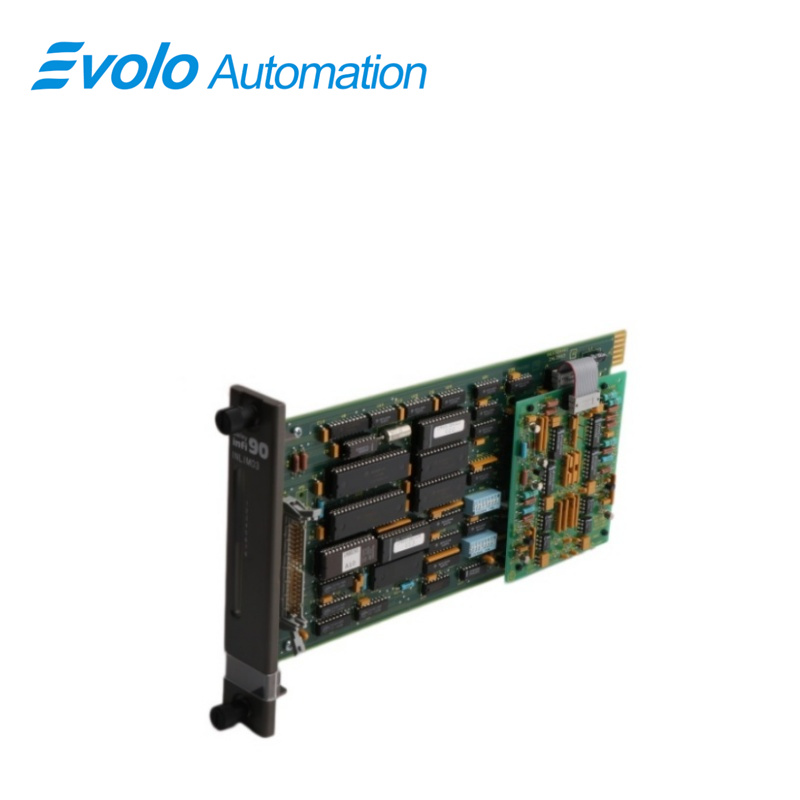
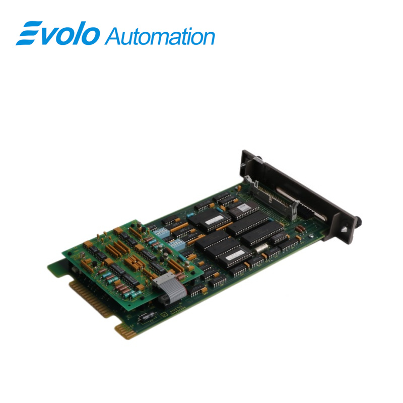
INLIM03 |
Packaging Details: |
Original new Factory Sealed |
Delivery Time: |
5-7 days |
Payment Terms: |
T/T |
Supply Ability: |
In stock |
Specifications
|
Parameter |
Value |
|
Model |
INLIM03 |
|
Description |
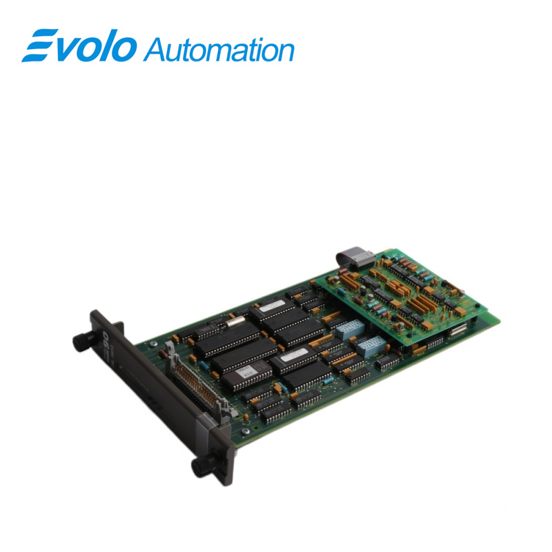
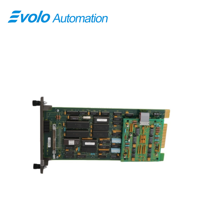
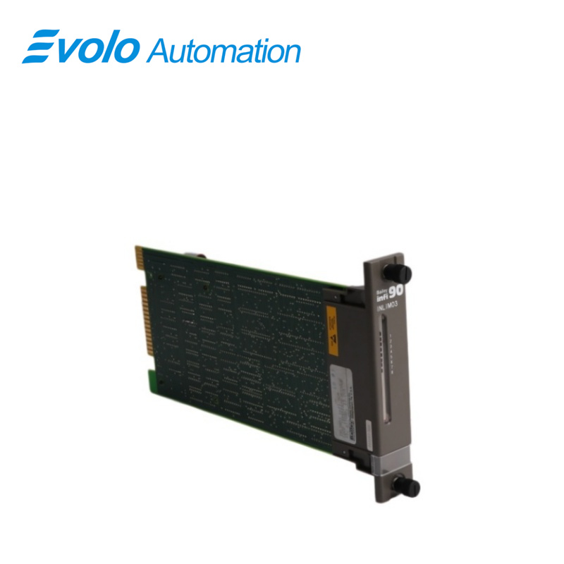
Bailey Infi 90 Loop Interface Module |
|
Dimension |
3.5x31x17.6 cm |
|
Weight |
0.4 kg |
|
Memory |
2 kB RAM; 4 kB ROM |
|
Power Requirements |
+5 VDC @ 2.0 A (10 W nominal); ±15 VDC @ 80 mA (1.2 W nominal) |
|
System Capability |
Up to 63 nodes (any combination of PCU, OIS, NIU) |
|
Communication Rates |
500 kbaud; up to 800 messages/second |
|
Synchronization Time |
100 ms maximum |
|
Cable Specifications |
Plant Loop: 2000 m max; Loop Interface: 61 m max |
|
Certification |
CSA certified for use in non-hazardous environments |
|
Operating Temperature |
0°C to 70°C (32°F to 158°F) |
|
Relative Humidity |
0% to 95% up to 55°C; 0% to 45% at 70°C (non-condensing) |
|
Atmospheric Pressure |
Sea level to 3 km (1.86 miles) |
Description
The INLIM03 Loop and Bus Interface Modules provide the principal communication interface between INFI 90 Process Control Units (PCU) and Plant Loop. Plant Loop is a high speed (500 kbaud) serial communication highway that all INFI 90 modules share. A maximum of 63 nodes, in any combination, can be on the loop. The INLIM03 are directly upward compatible with Network 90 NLIM02 and NBIM02. The basic function of the BIM is to gather data from modules and transfer it to the LIM. The basic function of the LIM is to examine the data and transmit it to the assigned destination on the loop. The INLIM03 each occupy one slot in the Module Mounting Unit (MMU). They are joined together with a ribbon cable. Two captive screws on each module secure them to the MMU. Eight LEDs on the LIM faceplate display messages and error information.
Applications
Power and Energy:
Applications: Boiler control, turbine monitoring, and automated management of generator sets in thermal power plants.
Function: Provides stable real-time communication in high-temperature and high-pressure environments to ensure the safety of power production.
Petroleum, Chemical, and Petrochemical Industries:
Applications: Pressure control of reactors, pipeline flow monitoring, and temperature regulation in refineries and chemical plants.
Function: Supports Safety Instrumented Systems (SIS) for critical processes, preventing overpressure or leakage risks due to data delays.
Pulp and Paper & Mining:
Applications: Speed synchronization control of large paper machines and automated scheduling of conveyor belts in mines.
Function: Maintains long-term hardware stability in harsh factory environments with high dust and vibration.
Food Processing and Manufacturing:
Applications: Packaging, filling, and batch production control in automated production lines.
Function: Simplifies data exchange processes and improves overall factory production efficiency.
FEATURES
The modular design of the LIM and BIM modules, as with all INFI 90 modules, allows for flexibility when creating a process management system strategy. An optional second LIM/BIM pair can be added to provide a redundancy feature to the system. One pair performs the primary interface function, while the other LIM/BIM pair is on standby. Should a primary failure occur, the secondary pair comes on-line without interrupting the process. Other features include selectable poll rates (the time between module output block checks), on-board diagnostics, and 32 kbytes of RAM available to the BIM user. Each LIM provides redundant loop interface and the physical media is redundant.
Physical Installation
1. Verify the slot assignments of the modules.
2. Connect the hooded end of the termination cable from the TU/TM to the MMU backplane. To do this, insert the connector into the backplane slot in the same slot as the one assigned to the LIM. The latches should snap securely into place.
3. After setting the switches on both modules, connect the Bailey supplied ribbon cable from the P4 connector on the LIM to the P4 connector on the BIM (see Figure 3-1). You are ready to install the modules. The LIM/BIM are inserted into adjacent guide rails of the Module Mounting Unit (MMU).
4. Align the module with the guide rails in the MMU; gently slide the module in until the front panel is flush with the top and bottom of the MMU frame.
5. Turn the two captive retaining screws a 1/2 turn on each module faceplate.
REPAIR/REPLACEMENT
1. Push and turn the two front panel captive retaining screws one half turn to unlatch the module. It is unlatched when the slots on the screws are vertical and the open end of the slots face away from the module.
2. Gently slide the module out of the MMU.
3. Configure the replacement module switch and jumper settings. Ensure they are set the same as the original module.
4. In the same slot assignment as the original module, align the replacement module with the plastic guide rails in the MMU; gently slide it in until the front panel is flush with the top and bottom of the MMU frame.
5. Push and turn the two captive retaining screws on the module faceplate one half turn to the latched position. It is latched when the slots on the screws are vertical and the open ends face the center of the module. (To remove the module, turn the module retaining screws to the unlatched position and gently slide out).
6. Return to normal operation.
FAQ
Q: What is INLIM03?
A: It is a Bailey Infi 90 Loop Interface Module.
Q:Can you ship the INLIM03 to my country?
A: Please don't worry ,We can ship the goods to worldwide.
Q: How many days the INLIM03 will arrive my hands if I place the order now?
A: As soon as we receive the payment, I will ship the products immediately.
It usually take 3-5 days from China to your hands.
Q: How to Check Price and Availability For INLIM03?
A: Please Contact John Yang for sales at +86-18150117685 or Request a Quote.