EN




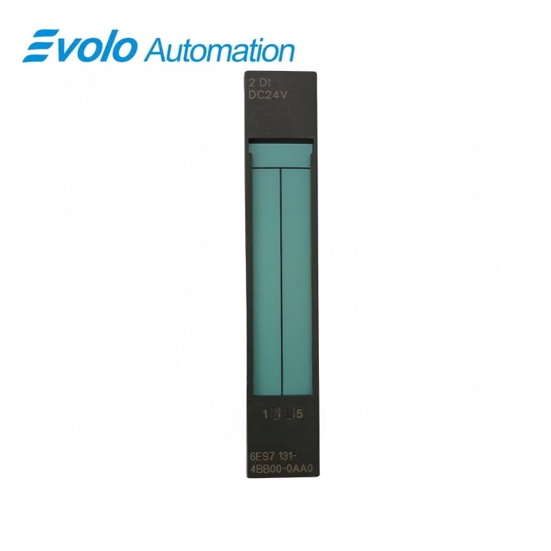
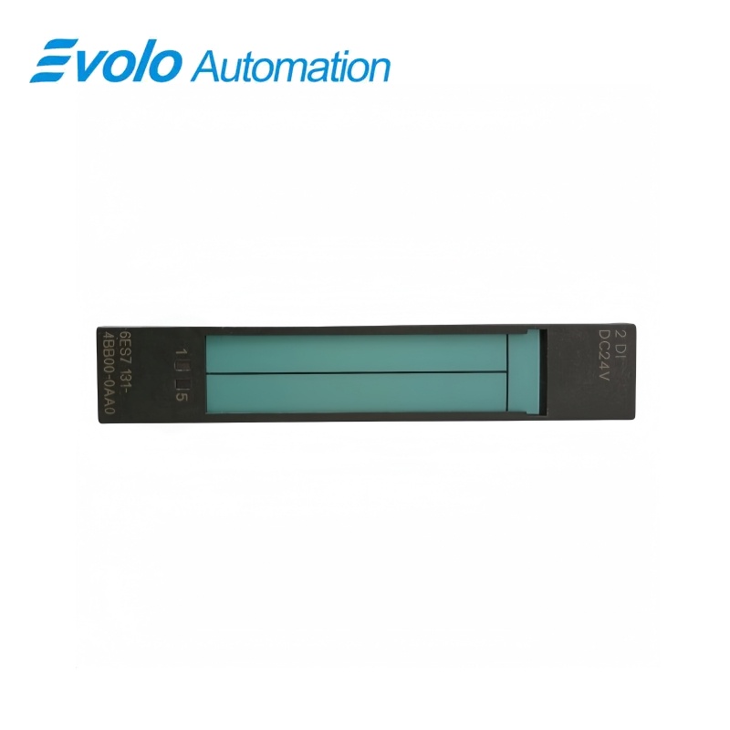
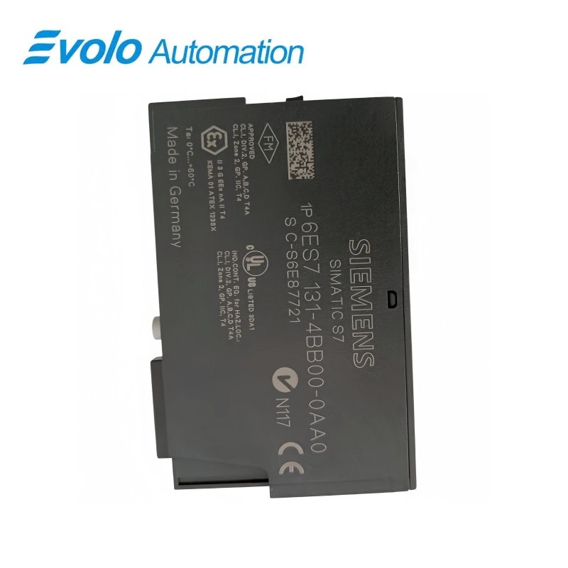
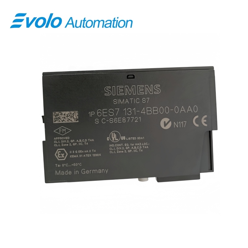
Siemens 6ES7131-4BB00-0AA0 SIMATIC ET 200S 2DI DC24V ST Digital Input Module
Manufacturer: Siemens
Condition: Brand New
Lead Time: In Stock
Origin: Germany
Warranty: 12 Months
Email: [email protected]
whatsApp: +86-18150117685
- Overview
- Hot Selling Models
- Recommended Products
Overview
- Use the 15–30 V ON threshold and −30 to +5 V OFF range.
- Keep two-wire sensor quiescent current at or below 1.5 mA.
- Allow for the specified input delay.
- Follow the actual terminal-module pattern for sensor supply and AUX1.
6ES7131-4BB00-0AA0 SIMATIC ET 200S 2DI DC24V ST Digital Input Module
A two-channel standard 24 V DC input module for switches and proximity sensors, with individual channel status indication.
At a Glance
| Brand | Siemens |
|---|---|
| Model | 6ES7131-4BB00-0AA0 |
| Product Type | Digital input module |
| Core Function | Discrete field-signal acquisition |
| Application | ET 200S sensor input stations |
Two field-input channels
Read switches or compatible proximity sensors through the ET 200S station.
Defined input thresholds
The signal-1 range is 15–30 V and the signal-0 range is −30 to +5 V.
Sensor supply provision
The module provides the documented supply connections for the selected sensor-wiring arrangement.
Product Overview
6ES7131-4BB00-0AA0 acquires two 24 V DC discrete input signals from switches or proximity sensors in an ET 200S station.
The standard input electronics combine per-channel green status indicators with a typical 3 ms input delay and a terminal-base-dependent two-, three- or four-wire sensor arrangement.
Key Functions
Acquire contact and sensor states
Two standard input channels accept rated 24 V DC signals with defined ON and OFF voltage ranges.
Supply compatible field sensors
The sensor-supply output provides up to 500 mA with a loaded output voltage of at least L+ minus 0.5 V.
Show individual input state
A green LED on each channel provides local status indication, while this standard version has no diagnostic function.
Official Specifications
| Input channel count | 2 |
|---|---|
| Rated input supply | 24 V DC from power module |
| Signal-1 input voltage | 15–30 V |
| Signal-0 input voltage | −30 to +5 V |
| Typical signal-1 input current | 7 mA at 24 V |
| Input transition delay | Typically 3 ms; 2.0–4.5 ms for both transitions |
| Input characteristic | IEC 61131 Type 1 |
| Maximum two-wire proximity-sensor quiescent current | 1.5 mA |
| Maximum unshielded and shielded cable lengths | 600 m and 1000 m respectively |
| Loaded sensor-supply output voltage | At least L+ minus 0.5 V |
| Sensor-supply output current | 0–500 mA; rated 500 mA |
| Typical module power dissipation | 0.4 W |
| Isolation arrangement | No channel-to-channel isolation; channels isolated from backplane bus |
| Permissible inter-circuit potential difference | 75 V DC or 60 V AC |
| Insulation test voltage | 500 V DC |
| Status indication | One green LED per input channel |
| Dimensions (W × H × D) | 15 × 81 × 52 mm |
| Approximate module weight | 35 g |
Frequently Asked Questions
Will a 12 V field signal reliably switch on an input of 6ES7131-4BB00-0AA0?
No, the specified signal-1 range starts at 15 V.
Can I connect a two-wire proximity switch to 6ES7131-4BB00-0AA0?
Yes, a two-wire proximity switch can be connected when its quiescent current does not exceed 1.5 mA.
Is 6ES7131-4BB00-0AA0 suitable for detecting very short high-speed pulses?
Its input delay is typically 3 ms and may range from 2.0 to 4.5 ms, so the pulse timing must accommodate that filtering.
Are the two input channels of 6ES7131-4BB00-0AA0 isolated from each other?
No, the channels are not mutually isolated, although they are isolated from the backplane bus.
How much sensor-supply current is available through 6ES7131-4BB00-0AA0?
The sensor-supply output is rated for 500 mA with a permissible range from 0 to 500 mA.
Will 6ES7131-4BB00-0AA0 provide the diagnostic functions of a High Feature input module?
No, this standard input module has no diagnostic function and uses green channel LEDs for local status.
Which terminals receive the two input signals on 6ES7131-4BB00-0AA0?
The input signals for channels 0 and 1 connect at terminals 1 and 5 respectively, with the remaining wiring determined by the selected terminal base.