EN




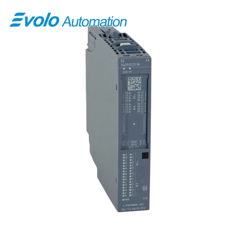
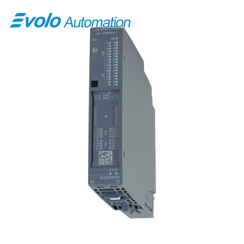
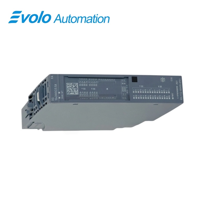
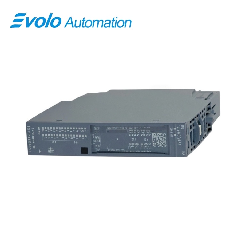
Siemens SIMATIC ET 200PA SMART+ 6DL1161-6BL00-0PH1 DI 32x24VDC PA
Manufacturer: Siemens
Condition: Brand New
Lead Time: In Stock
Origin: Germany
Warranty: 12 Months
Email: [email protected]
whatsApp: +86-18150117685
- Overview
- Hot Selling Models
- Recommended Products
Overview
- Use PCS 7 V9.1 SP2 or later, or PCS neo V4.1 or later, for the supported engineering path.
- Do not plan the module as a STEP 7 TIA Portal or classic STEP 7 device without a separately verified system solution.
- Choose the terminal block for the intended 1-wire or 2-wire sensor arrangement and encoder-supply requirement.
- A light-gray terminal block starts a new potential group, a dark-gray block continues it and a black block is supplied individually.
- Confirm that the application does not require I/O redundancy because this module is not redundancy-capable.
- Match the complete article number and verify cable shielding, signal thresholds, wire-break settings and ambient-temperature limits before commissioning.
6DL1161-6BL00-0PH1 DI 32x24VDC PA
A 32-channel 24 V DC digital input module for process-signal acquisition in SIMATIC ET 200PA SMART+ stations.
At a Glance
| Brand | Siemens |
|---|---|
| Model | 6DL1161-6BL00-0PH1 |
| Product Type | DI 32x24VDC PA digital input module |
| Core Function | 32-channel 24 V DC process-signal acquisition |
| Compatible Series | SIMATIC ET 200PA SMART+ |
Exact Identification
Match the complete article number 6DL1161-6BL00-0PH1 and the DI 32x24VDC PA designation.
Signal Profile
P-reading source/sink inputs use IEC 61131 type 1 and type 3 input characteristics.
Engineering Baseline
Plan for PCS 7 V9.1 SP2 or PCS neo V4.1 and verify the terminal-block arrangement.
Product Overview
6DL1161-6BL00-0PH1 is the Siemens SIMATIC ET 200PA SMART+ DI 32x24VDC PA digital input module for acquiring 32 binary process signals at 24 V DC.
The module supports individually activated channels, channel-by-channel diagnostic alarms and hardware interrupts for rising or falling signal edges, plus wire-break monitoring for field circuits.
Channel status LEDs show the input level, while module diagnostics and the PWR indication support commissioning and maintenance inside the distributed I/O station.
Key Functions
Dense Process Input Acquisition
The 22.5 mm-wide module handles 32 binary process inputs and allocates four input bytes plus four bytes of quality information.
Channel-Level Event and Fault Handling
Each channel can provide diagnostic alarms and rising- or falling-edge hardware interrupts, while wire-break monitoring can be enabled for field troubleshooting.
Flexible Sensor Wiring
The module supports 1-wire and 2-wire sensor arrangements, and the compatible terminal-block selection determines encoder-supply and potential-group behavior.
Official Specifications
| Engineering Integration | PCS 7 V9.1 SP2; PCS neo V4.1 |
|---|---|
| Supply Voltage Range | 19.2 to 28.8 V DC |
| Module Current Consumption | 11.5 mA rated; 15 mA maximum |
| Power Loss | 1.6 W typical; 2.8 W maximum with all inputs at signal 1 |
| Process Image Allocation | 4 bytes plus 4 bytes for quality information |
| Input Characteristic | Source/sink P-reading; IEC 61131 type 1 and type 3 |
| Signal 0 Input Voltage | -30 to +5 V |
| Signal 1 Input Voltage | +11 to +30 V |
| Signal 1 Input Current | 2.5 mA typical |
| Rising Signal Delay | 3.2 ms minimum; 5.3 ms maximum |
| Falling Signal Delay | 2.9 ms minimum; 4.5 ms maximum |
| Cable Length | 1,000 m shielded; 600 m unshielded |
| 2-Wire Sensor Quiescent Current | 1.5 mA maximum |
| Diagnostic and Process Alarms | Channel-by-channel diagnostic alarms and hardware interrupts |
| Supply and Wire-Break Monitoring | Module-wise supply monitoring; channel-by-channel wire-break monitoring with an optional 15 to 18 kΩ protective circuit for simple encoder contacts |
| Electrical Isolation | Channels isolated from the backplane bus; tested at 1,500 V DC for 1 minute |
| Operating Temperature by Mounting | -40 to +70 °C horizontal; -40 to +60 °C vertical |
| Dimensions | 22.5 × 115 × 138 mm (W × H × D) |
| Approximate Weight | 150 g |
Frequently Asked Questions
Which engineering software supports 6DL1161-6BL00-0PH1?
The module is integrated from PCS 7 V9.1 SP2 and PCS neo V4.1, while STEP 7 TIA Portal and classic STEP 7 are not listed as supported engineering routes.
Can I connect a 2-wire sensor to 6DL1161-6BL00-0PH1?
The module accepts 2-wire sensors with a permissible quiescent current of up to 1.5 mA when the wiring and terminal block are selected correctly.
How far can I run field wiring from 6DL1161-6BL00-0PH1?
The maximum documented cable length is 1,000 m with shielded cable or 600 m with unshielded cable.
Which voltage levels does 6DL1161-6BL00-0PH1 interpret as signal 0 and signal 1?
The input interprets -30 to +5 V as signal 0 and +11 to +30 V as signal 1.
Can 6DL1161-6BL00-0PH1 report rising and falling edges separately?
The module can generate channel-by-channel hardware interrupts for rising edges, falling edges or both signal changes.
What should I check if 6DL1161-6BL00-0PH1 reports a wire break?
Wire-break diagnostics operate by channel, and simple encoder contacts can use an optional 15 to 18 kΩ protective circuit to prevent unwanted indications.
Which mounting temperatures are allowed for 6DL1161-6BL00-0PH1?
The permitted operating range is -40 to +70 °C for horizontal mounting and -40 to +60 °C for vertical mounting.