EN
EN




- Overview
- Specifications
- Description
- Applications
- Compatibility
- Mounting instructions
- FAQ
- Recommended Products
Overview
Place of Origin: |
Sweden |
Brand Name: |
ABB |
Model Number: |
NMBP-01 |
Packaging Details: |
Original new Factory Sealed |
Delivery Time: |
5-7 days |
Payment Terms: |
T/T |
Supply Ability: |
In stock |
Specifications
|
Parameter |
Specification |
|
Model |
NMBP-01 |
|
Device Type |
Modbus Plus Adapter Module |
|
Compatible Devices |
ABB Fieldbus Adapter Modules, ABB ACS 300, ACS/H 400, ACS/ACPIACF 600, DCS 500 Drives |
|
Link Size |
2 stations (up to 9 in Multiple Drive Control) |
|
Medium |
Fiber optic cable |
|
Cable Construction |
Plastic core, 1 mm diameter, sheathed with plastic jacket |
|
Cable Attenuation |
0.31 dB/m |
|
Maximum Length Between Stations |
10 m |
|
Topology |
Point-to-point (Ring in Multiple Drive Control) |
|
Serial Communication Type |
Synchronous, half duplex |
|
Transfer Rate |
4 Mbit/s |
|
Protocol |
Distributed Drives Communication System (DDCS) |
|
Connectors |
Blue – receiver; Grey – transmitter |
|
Enclosure |
Plastic, 71 × 35 × 140 mm (H×W×D), IP20 |
|
Mounting |
Standard DIN mounting rail |
|
Settings |
Via drive interface (control panel) |
|
Current Consumption |
80 mA at 24 V DC |
|
Operating Temperature |
0 °C to +50 °C |
|
Operating Humidity |
5–95 %, no condensation (max 60 % with corrosive gases) |
|
Storage Temperature |
-40 °C to +70 °C |
|
Storage Humidity |
Less than 95 %, no condensation |
|
Atmospheric Pressure |
70 to 106 kPa |
|
Vibration |
Max 0.3 mm (2–9 Hz), max 1 m/s² (9–200 Hz sinusoidal) |
|
Shock |
Max 100 m/s², 11 ms |
|
Short Term Tensile Force |
50 N |
|
Short Term Bend Radius |
25 mm |
|
Long Term Bend Radius |
35 mm |
|
Flexing |
1000 cycles |
Description
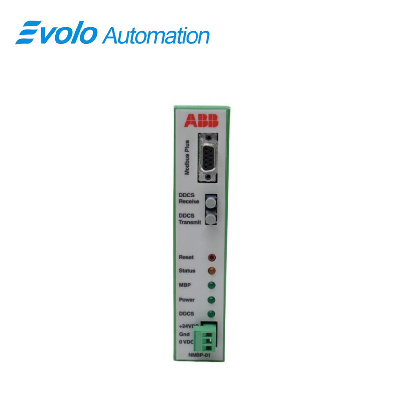
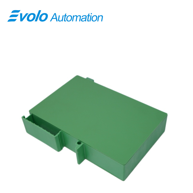
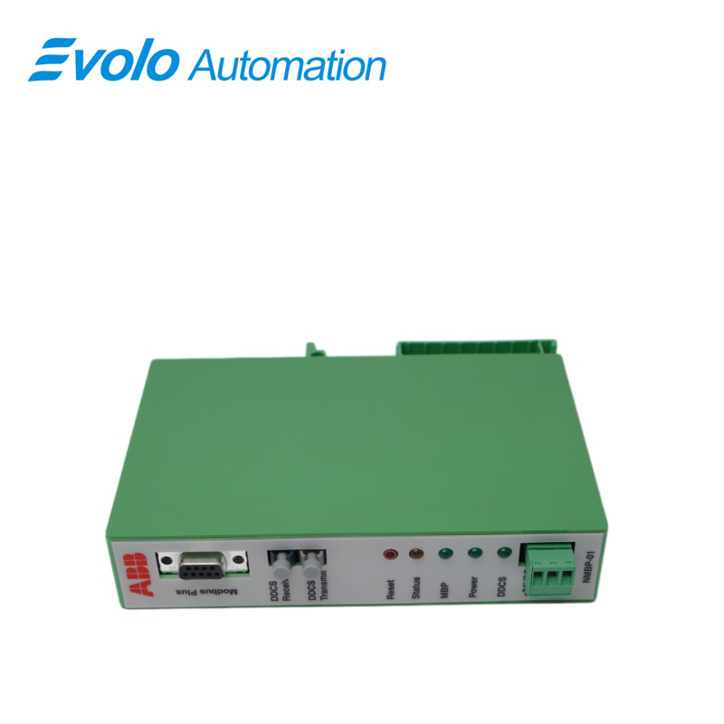
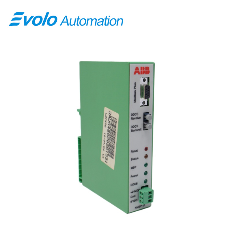
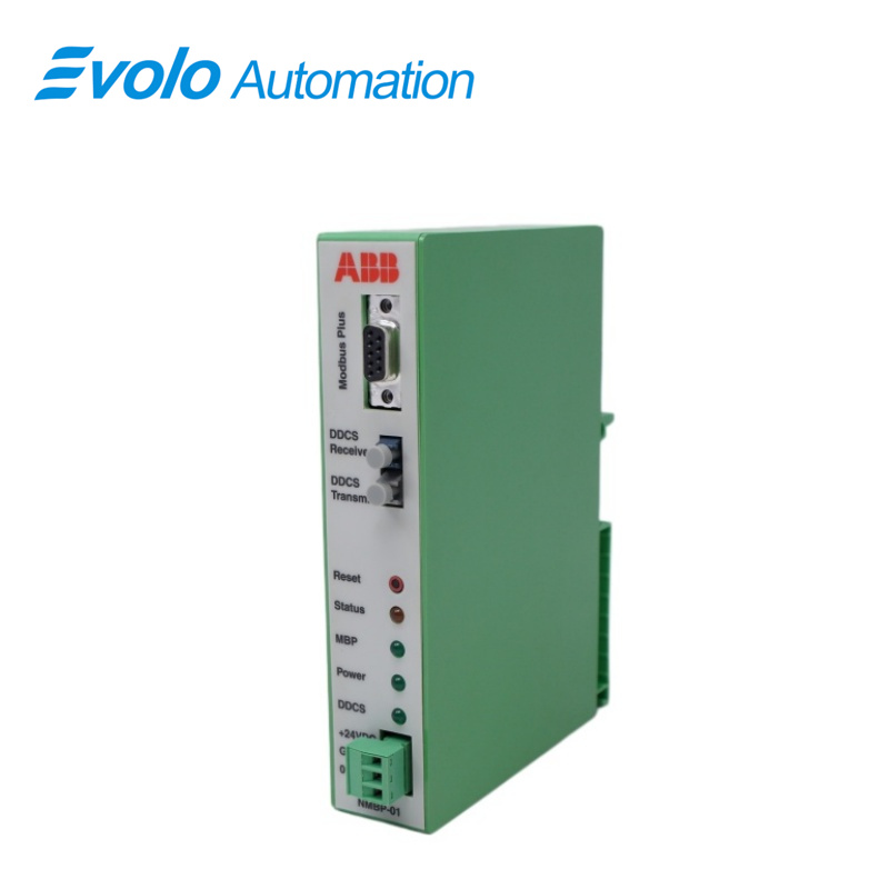
The NMBP-01 Modbus Plus Adapter Module is for connecting the ABB drive directly to the Modicon Modbus Plus network. The NMBP-01 supports read and write access to the drive parameters and data sets, as well as receiving and sending global data for critical drive control and feedback values. The NMBP-01 Modbus Plus Adapter Module is an optional device for ABB drives which enables the connection of the drive to a Modbus Plus system. The drive acts like a Modicon PLC on the network. The adapter module is mounted onto a standard mounting rail inside or outside the drive unit, depending on drive type and configuration. See the user's manual of the drive for module placement options.
Applications
Steel/Metallurgical Plants: Blast furnace main drive, rolling mill control cabinets.
Paper/Pulp Mills: Inverter units for the drive systems of large paper machines.
Oil/Chemical Plants: Variable frequency drive systems for driving high-power compressors and water injection pumps.
Compatibility
The NMBP-01 has been tested and approved by Modicon as a part of the ModConnect program acceptance. The NMBP-01 is compatible with:
ACS 400
ACS 600 SingleDrive
ACS 600 MultiDrive
ACS 600 MotionControl (ACP 600)
ACS 600 CraneDrive(ACC 600)
ACS 600 Pump and Fan Drive
(ACF 600)
DCS 500(software version 21x 226 or later)
Mounting instructions
Mounting Inside the Drive:
1 Stop the drive.
2 Switch off the power supply of the drive and all dangerous voltages connected to the inputs and outputs.
3 Wait for five minutes to ensure that the capacitors in the intermediate circuit have discharged.
4 Remove the front cover of the drive.
5 Ensure that the input power cable, motor cable and capacitor bank(UDC+ and UDC-) are not powered.
6 Locate the position for the module (see the user's manual of the drive). Fasten the mounting rail to its place if not already installed. Observe the free space requirements for the module (min. 10 mm from adjoining equipment/wall).
7 Push the module onto the rail. The module can be released by pulling the locking spring with a screwdriver.
FAQ
Q: Can a damaged NMBP-01 be partially repaired?
A: Not recommended. The baseboard has a multi-layered circuit design, making internal open circuits difficult to detect visually. To ensure the safety of high-power equipment, complete replacement is generally recommended.
Q: Do I need to adjust the DIP switches when replacing the NMBP-01?
A: No. The baseboard itself typically does not have logic settings; all parameters and address definitions are determined by the daughterboards or main control boards plugged into it.
Q: Why does my inverter report "INT Board Error" but replacing the NINT board doesn't help about NMBP-01?
A: In this case, the fault is most likely on the NMBP-01 baseboard, meaning the signal is lost in the baseboard's transmission path.
Q: Are NMBP-01 and NMBP-02 interchangeable?
A: No. Different models have different physical dimensions and slot definitions; you must strictly check against the original spare parts list.
Q: Are there any special requirements during installation about NMBP-01?
A: You must ensure that all fixing screws are installed. Some screws also serve as grounding (GND) leads; failure to install them may result in strong electromagnetic interference.