EN
EN




- Overview
- Specifications
- Description
- Applications
- SPECIAL HANDLING
- MODULE REPLACEMENT
- FAQ
- Recommended Products
Overview
Place of Origin: |
Sweden |
Brand Name: |
ABB |
Model Number: |
NIMF02 |
Packaging Details: |
Original new Factory Sealed |
Delivery Time: |
5-7 days |
Payment Terms: |
T/T |
Supply Ability: |
In stock |
Specifications
|
Parameter |
Specification |
|
Model |
NIMF02 |
|
Device Type |
Bailey Multi-Function Controller Termination Module |
|
Dimensions |
3.4 × 17.7 × 17.7 cm |
|
Weight |
0.24 kg |
|
Power Requirements |
+24 V DC |
|
Current Consumption |
160 mA max (LED consumes 10 mA) |
|
Communication |
2 × RS-232-C ports; 1 × serial link for stations |
|
Cable Insulation |
PVC (UL CL2) 80 °C at 300 V; Non-PVC (UL PLTC) 90 °C at 300 V |
|
Mounting |
Single slot in termination mounting unit |
|
EMI/RFI Precautions |
Keep cabinet doors closed; maintain ≥2 m distance from communication equipment |
|
Cooling Requirements |
No cooling required within specified limits |
|
Operating Temperature |
0 °C to +70 °C |
|
Humidity |
5–90 % up to 55 °C; 5–90 % up to 70 °C (non-condensing) |
|
Altitude |
Sea level to 3 km |
|
Air Quality |
Non-corrosive environment |
|
Certification |
CSA certified for process control equipment in non-hazardous locations |
Description
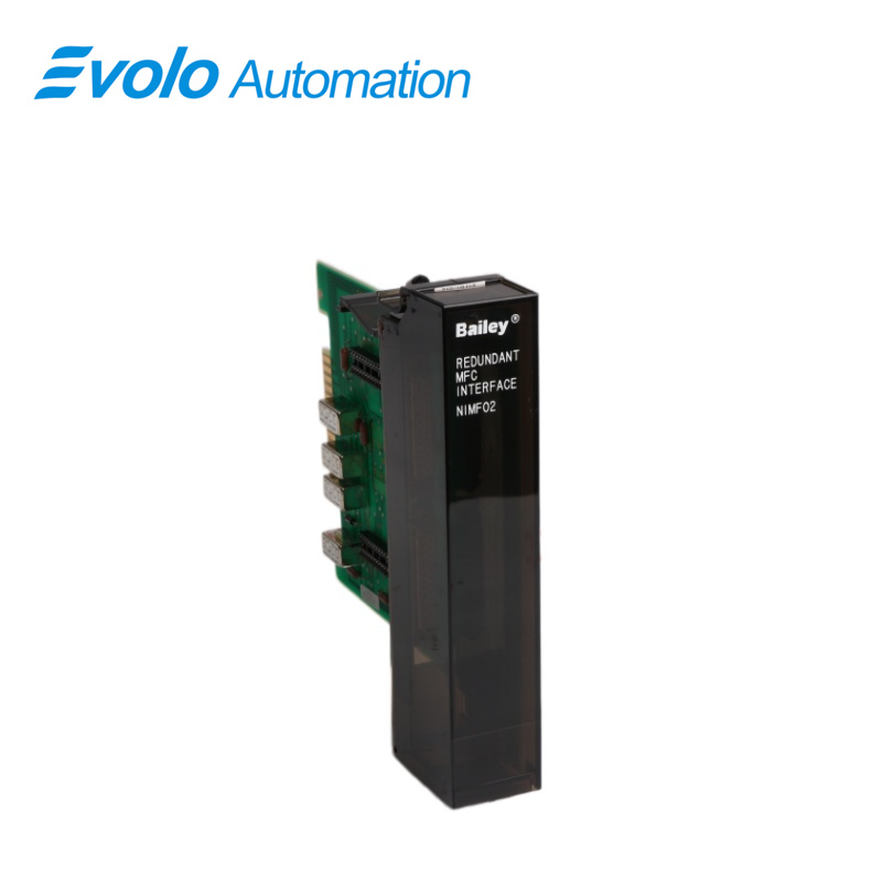
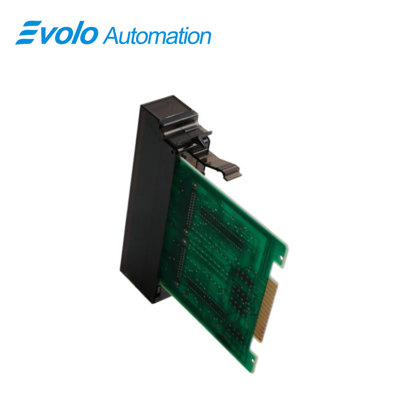
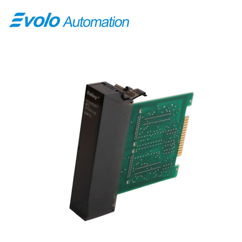
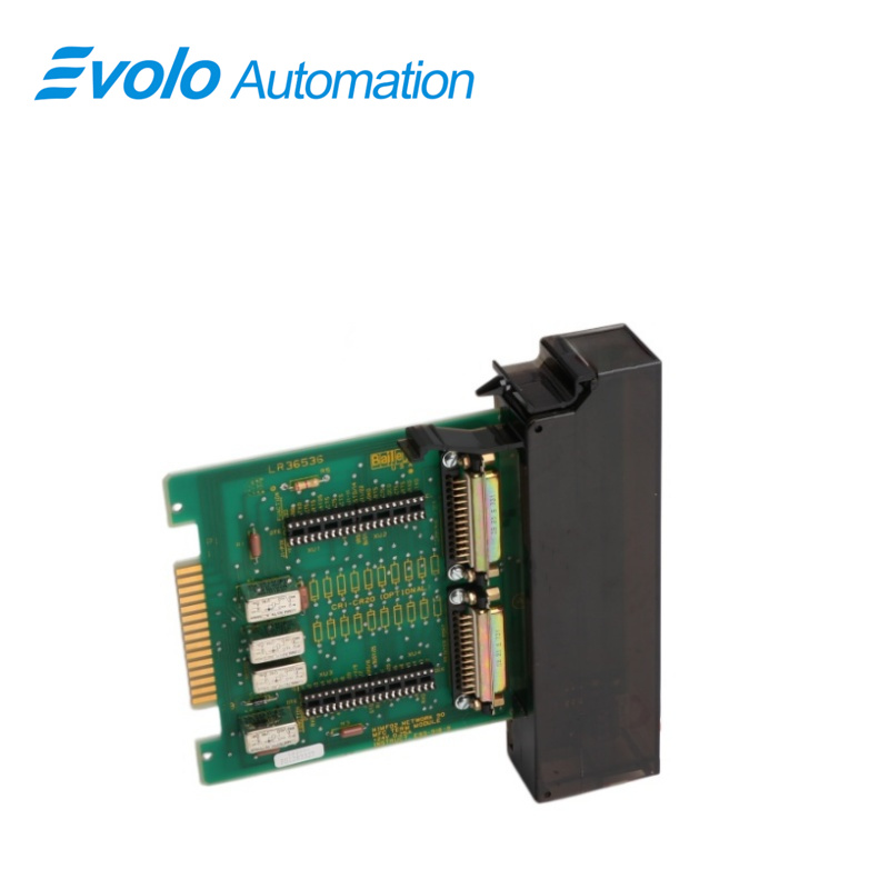
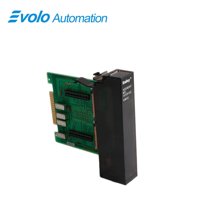
Termination modules provide a connection from the plant equipment to the INFI 90® process modules. The NIMF02 Multi-Function Controller Termination Module is used in addition to the NIMF01 termination module when terminating redundant modules. This product instruction explains how to install and use the NIMF01 and NIMF02 Multi-Function Controller Termination Modules. The NIMF02 termination module is used in addition to the NIMF01 termination module when terminating redundant modules. The NIMF02 has on-board relays that allow one MFC module to communicate over the RS-232-C link during redundant operation.
Applications
Large thermal power plants: Boiler combustion control and turbine coordinated control system (CCS).
Oil refineries: Closed-loop control of core processes such as distillation columns and reactors.
Steel plants: High-precision temperature and pressure regulation of blast furnaces and converters.
Chemical processing plants: Automated processes with extremely high requirements for safety interlocks and continuous production.
SPECIAL HANDLING
1. Use Static Shielding Bag. Keep the modules in the static shielding bag until you are ready to install them in the system. Save the bag for future use.
2. Ground Bag Before Opening. Before opening a bag containing an assembly with CMOS devices, touch it to the equipment housing or a ground to equalize charges.
3. Avoid Touching Circuitry. Handle assemblies by the edges; avoid touching the circuitry.
4. Avoid Partial Connection of CMOS Device. Verify that all devices connected to the modules are properly grounded before using them.
5. Ground Test Equipment.
6. Use an Antistatic Field Service Vacuum. Remove dust from the module if necessary.
7. Use a Grounded Wrist Strap. Connect the wrist strap to the appropriate grounding plug on the power entry panel. The grounding plug on the power entry panel is connected to the earth grounding electrode system through the AC safety ground.
8. Do Not Use Lead Pencils to Set Dipswitches. To avoid contamination of dipswitch contacts that can result in unnecessary circuit board malfunction, do not use a lead pencil to set a dipswitch.
MODULE REPLACEMENT
1. Pull the termination module out of the TMU so that the RS-232-C and power cables are accessible.
2. Turn off power to the cabinet and disconnect the +24 VDC, common and chassis ground wiring from TB1, TB2 and TB3 of the termination module. Mark the cables according to their terminal assignments as you remove them.
3. If there is a serial link to a station termination module, disconnect the serial link from TB29 and TB30. Mark the cables according to their terminal assignments as you remove them. The NIMF02 does not have a serial link connection.
4. If there is a redundant termination module (an NIMF01 and NIMF02) disconnect the ribbon cable from the J3 socket on the faulty termination module.
5. Remove the RS-232-C cables from the DB-25 connectors on the faulty IMF termination module. Mark the cables according to their connector assignments as you remove them.
6. When all cables are removed from the termination module, pull it out of the TMU unit.
7. Align the replacement termination module with the guide rails of its assigned slot in the TMU unit.
8. Partially insert the replacement termination module and connect the RS-232-C cables, power wiring, serial link and ribbon cable.
9. After all cables and wires have been replaced, slide the termination module into the TMU unit until its card edge seats in the card edge connector of the termination module cable on the backplane of the TMU unit.
10. Return power to the computer, modem or diagnostic terminal. Return power to the cabinet containing the IMF termination module.
FAQ
Q: What is NIMF02?
A: It is a Bailey Multi-Function Controller Termination Module.
Q: Can NIMF02 directly replace NIMF01?
A: NIMF02 is usually an enhanced version with larger memory or faster processing speed and better backward compatibility. However, firmware version requirements must be checked before replacement.
Q: Why won't the program run on the new board NIMF02?
A: The program is usually stored in a pluggable EPROM. If the new board does not have the chip with the original program, it will not be able to execute specific factory logic.
Q: How many I/O slaves can NIMF02 support?
A: It depends on the system configuration. Typically, 10-64 I/O modules can be mounted in a control rack.
Q: How to perform a cold start about NIMF02?
A: Use the Reset button on the front panel in combination with a specific DIP switch. Refer to the system's maintenance manual for specific steps.