EN
EN




- Overview
- Specifications
- Description
- Applications
- Compatability
- Installation
- Operation
- Characteristics
- FREQUENTLY ASKED QUESTIONS
- Recommended Products
Overview
Place of Origin: |
USA |
Brand Name: |
GE |
Model Number: |
IS200TTURH1B |
Packaging Details: |
Original new Factory Sealed |
Delivery Time: |
5-7 days |
Payment Terms: |
T/T |
Supply Ability: |
In stock |
Specifications
|
Part Number: |
IS200TTURH1B |
|
Manufacturer: |
General Electric |
|
Country of Origin: |
USA |
|
Function: |
Turbine Protection Input Terminal Board |
|
Series: |
Mark VI |
|
Number of Inputs: |
12 |
|
Number of Outputs: |
5 A at 125 V DC |
|
Operating Temperature: |
-30 to 65 °C |
|
Power Supply Voltage: |
125 V DC |
|
Technology: |
Surface Mount |
|
Dimensions: |
33 x 17.7 x 5.5 cm |
|
Weight: |
1.1 kg |
|
Shaft Voltage: |
5 V DC |
|
MPU Pulse Rate Range: |
2 Hz to 20 kHz |
|
MPU Pulse Rate Accuracy: |
0.05% |
|
MPU Input Circuit Sensitivity: |
27 mV pk |
|
Shaft Voltage Monitor: |
5 V DC pulses 0-2,000 Hz |
|
Shaft Voltage Wiring: |
Up to 300 m, max 15 ohms |
|
Shaft Voltage DC Test: |
5 V DC source, measures current |
|
Shaft Voltage AC Test: |
1 kHz test voltage |
|
Shaft Current Input: |
AC amps, shunt voltage up to 0.1 V pp |
Description
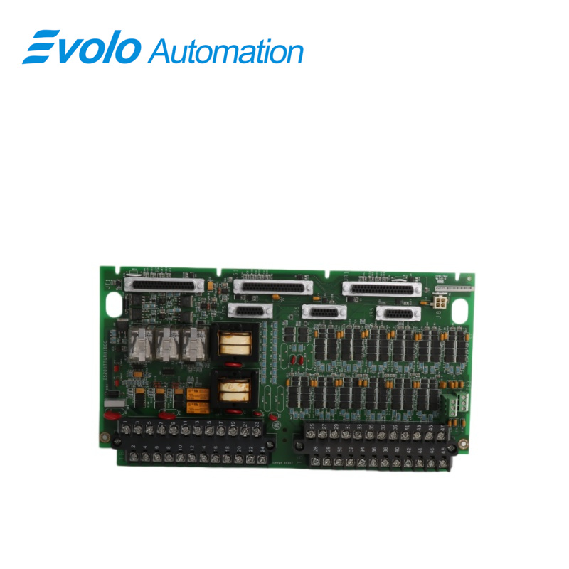
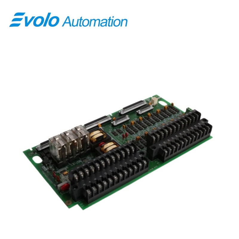
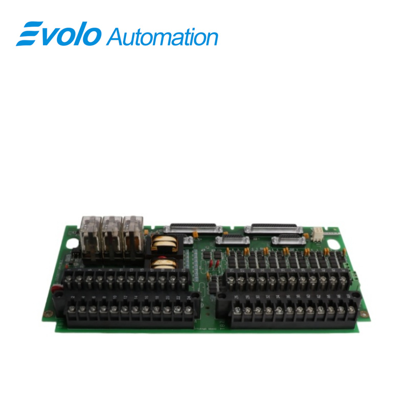
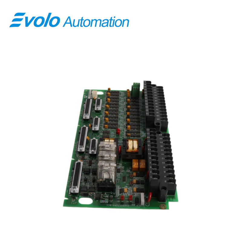
IS200TTURH1B is a Primary Turbine Protection Input terminal board developed by GE. TTUR has three relays, K25, K25P, and K25A, all of which must close in order to provide 125 V dc power to the main breaker, 52G. The JR5 connector is used for the speed signal cable to VTUR, and the JR1 connector is used for the other signals. Signals from TMR systems fan out to the JR5, JS5, JT5, JR1, JS1, and JT1 connectors.
Applications
Thermal power plants (gas turbines): Widely used in GE Frame 6, 7, and 9 series units. It is the most critical board in the Mark VI cabinet responsible for the "start-up, operation, and protection" logic.
Combined cycle power plants (CCGT): Serves as the physical interface for speed and synchronization logic in complex turbine control loops.
Large industrial captive power plants: Such as steel mills or large chemical plants, used to ensure safe speed control of high-power turbine drives.
Compatability
1 Terminal board is compatible with VTUR and features the following inputs and outputs.
2 Twelve passive pulse rate devices sensing a toothed wheel to measure turbine speed.
3 Generator voltage and bus voltage signals from potential transformers.
4 125 V DC output to the main breaker coil for automatic generator synchronization.
Installation
1 TTUR Terminal Board Wiring: Connect the wires for the magnetic pick-ups, shaft pick-ups, potential transformers, and breaker relays to the two I/O terminal blocks TB1 and TB2.
2 Each block is held together with two screws and has 24 terminals that accept wires up to #12 AWG. To the left of each terminal block is a shield termination strip connected to the chassis ground. Jumpers JP1 and JP2 are used to select SMX or TMR for relay drivers K25 and K25P.
3 Connect the wires for optional TTL active speed pick-ups to TB3 if they are used; these require an external power supply.
Operation
1 To measure turbine speed in simplex applications, up to four pulse rate signals can be used. TTUR receives generator and bus voltages for automatic synchronization with VTUR, the turbine controller, and the excitation system. TTUR controls the main breaker relay coil, 52G, and has permissive generator synchronizing relays.
2 All inputs in TMR applications fan to the three control racks. Control signals from R, S, and T are voted before they activate permissive relays K25 and K25P in TTUR.
3 The VPRO and TREG boards control relay K25A.
Characteristics
1 Number of outputs: Generator breaker coil, 5 A at 125 V DC.
2 Power supply voltage: Nominal 125 V DC to breaker coil.
3 MPU pulse rate range: 2 Hz to 20 kHz.
4 MPU pulse rate accuracy: 0.05% of reading.
5 MPU input circuit sensitivity: 27 mV pk (detects 2 rpm speed).
6 Shaft voltage monitor: Signal is the frequency of 5 V DC (0-1 MHz) pulses from 0 to 2,000 Hz.
7 Shaft voltage wiring: Up to 300 m (984 ft), with maximum two-way cable resistance of 15 ohms.
8 Shaft voltage DC test: Applies a 5 V DC source to test the integrity of the external turbine circuit and measures DC current flow.
9 Shaft voltage AC test: Applies a test voltage of 1 kHz to the input of the VTUR shaft voltage circuit (R module only).
10 Shaft current input: Measures shaft current in amps AC (shunt voltage up to 0.1 V pp).
FREQUENTLY ASKED QUESTIONS
Q: What is IS200TTURH1B?
A: IS200TTURH1B is a Primary Turbine Protection Input terminal board developed by GE.
Q: What is the power supply voltage to the breaker coil of IS200TTURH1B?
A: The nominal power supply voltage to the breaker coil is 125 V DC.
Q: What is the MPU pulse rate range of the component of IS200TTURH1B?
A: The MPU pulse rate ranges from 2 Hz to 20 kHz.