EN
EN




- Overview
- Specifications
- Description
- Applications
- Features
- Application Data
- Frequently Asked Questions
- Recommended Products
Overview
Place of Origin: |
USA |
Brand Name: |
GE |
Model Number: |
IS200ESELH1A IS200ESELH1AAA |
Packaging Details: |
Original new Factory Sealed |
Delivery Time: |
5-7 days |
Payment Terms: |
T/T |
Supply Ability: |
In stock |
Specifications
|
Part Number |
IS200ESELH1A, IS200ESELH1AAA |
|
Manufacturer |
General Electric |
|
Country of Manufacture |
United States of America (USA) |
|
Series |
EX2100 |
|
Product Type |
Exciter Selector Board |
|
Dimensions |
26.04 x 1.99 x 18.73 cm |
|
Maximum Lead Resistance |
15 ohm |
|
Keyphasor Probes |
2 |
|
Current Inputs from Pyrometers |
4-20 mA |
|
Keyphasor Input Voltage |
0.5-20 V dc |
|
Cable Drives to EGPA |
6 |
|
Input Source |
Provided via EMIO (Main I/O Board) |
Description
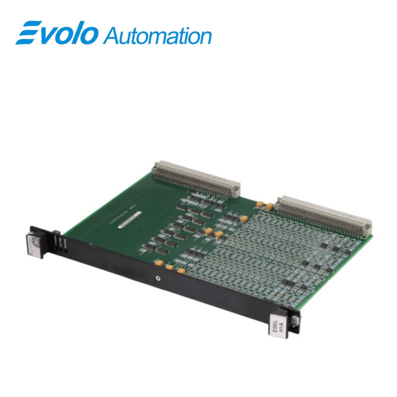
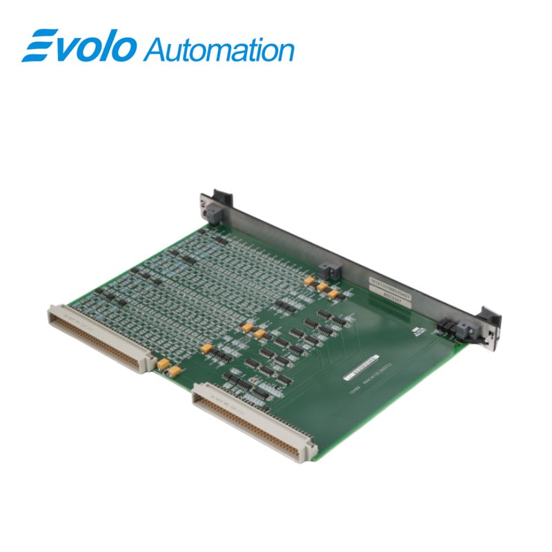
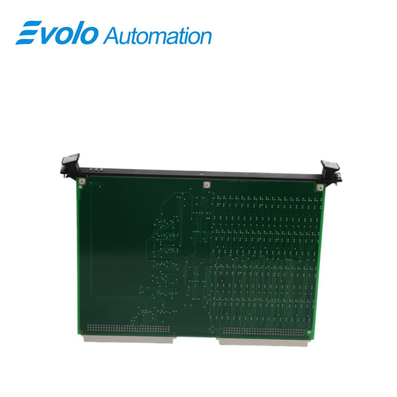
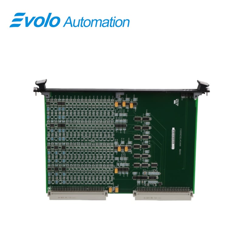
IS200ESELH1A IS200ESELH1AAA is an Exciter Selector Board developed by GE. It is a part of EX2100 control system. The board is mounted within the control rack, a central hub for managing various control and signaling functions within the excitation system.It integrates seamlessly with the control rack.ensurina stable and secure placement. which is vital for the reliable operation of the exciter system.
Applications
Power generation: EX2100 excitation system for gas turbines, steam turbines, and hydroelectric power generation systems.
Redundant architecture: In redundant control systems, two ESEL boards are typically installed (driven by controllers 1 and 2 respectively), with controller C selecting the currently active board.
Plant environment: Commonly found in power plants, petrochemical plants, and other facilities with large synchronous generator sets, integrated into the control cabinet via a stable VME bus connection.
Features
1 Logic Level Gate Pulse Signals: The board receives six logic level gate pulse signals from its corresponding Master I/O (EMIO) board. These signals are critical for controlling the timing and operation of the exciter.
2 Signal Conversion: Upon receiving the gate pulse signals, the board processes these signals to ensure they are appropriately formatted and timed for further distribution.
3 Cable Distribution: The processed gate pulse signals are then used to drive six sets of cables. These cables are responsible for transmitting the signals to the Exciter Gate Pulse Amplifier (EGPA) boards.
4 Signal Integrity: The design ensures that the integrity of the signals is maintained during transmission, preventing signal degradation or loss which could impact the performance of the excitation system.
5 Interaction with EGPA Boards: The Exciter Gate Pulse Amplifier (EGPA) boards are critical components mounted in the Power Conversion Cabinet. They amplify the gate pulse signals received from the board to levels required for driving the power devices in the excitation system.
6 Power Conversion Cabinet: This cabinet houses the EGPA boards and other related power conversion components. It is designed to manage high-power electrical signals and convert them into usable forms for the excitation system.
Application Data
1 Jumpers and Testpoints: The board is designed without any jumpers or testpoints, simplifying its design and reducing potential points of failure. This design choice streamlines the board's installation and maintenance.
2 Connectors, P1 and P2: These connectors link to VME (Versa Module Europa) backplane. The specific pin signals for these connectors are not detailed in this document, as they are typically not required during routine troubleshooting. The connectors ensure that the board integrates seamlessly with the overall system architecture, allowing for efficient communication and power distribution.
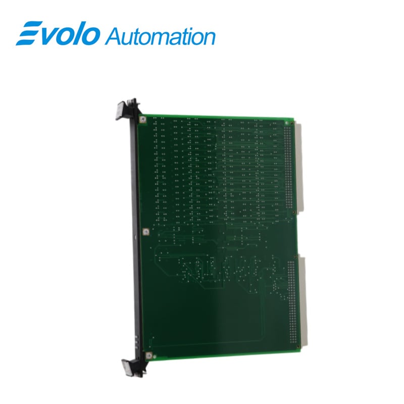
3 Layout: The layout of the ESEL board is designed for optimal performance and ease of access. The layout is illustrated in the accompanying figure, which provides a visual representation of the board's components and their arrangement.
4 Status Indicators: The board includes three green LEDs located at the top of the front panel. These LEDs provide critical status information, enabling quick visual confirmation of the board's operational state. The functions of these LEDs are as follows:
Power Indicator: This LED illuminates to indicate that the board is receiving power, confirming that the board is correctly installed and electrically connected, ensuring it is ready for operation.
Board Active Indicator: This LED lights up when the board is active, signifying that it has been enabled by a control signal from the control C. This indicates that the board is operational and integrated into the system's control logic.
Board Gating Indicator: This LED is driven by gate inputs from the EMIO board. It lights up to indicate that the board is actively gating, meaning it is processing and transmitting gate pulse signals to the Exciter Gate Pulse Amplifier (EGPA) boards. This status confirms that the ESEL board is fulfilling its role in signal distribution and amplification.
Frequently Asked Questions
Q: What is IS200ESELH1A IS200ESELH1AAA?
A: It is an Exciter Selector Board developed by GE under the EX2100 series.
Q: What is ESEL redundancy, and why is it important of IS200ESELH1A IS200ESELH1AAA?
A: Redundancy refers to the provision of redundant units in control systems. It is crucial for ensuring system reliability and fault tolerance, minimizing downtime, and maintaining uninterrupted operation in the event of component failures.
Q: How many units are required in simplex systems of IS200ESELH1A IS200ESELH1AAA?
A: In simplex systems, only one unit is necessary. This configuration is suitable for basic operational requirements where redundancy control or online repair is not essential.
Q: Why are two ESEL provided in certain cases of IS200ESELH1A IS200ESELH1AAA?
A: In scenarios where redundancy control or online repair capabilities are required, two units are supplied. This setup enhances system resilience by providing backup functionality in case of unit failure or maintenance needs.