EN
EN




- Overview
- Quick Detail
- Description
- Applications
- Offline Replacement
- Online Replacement(Redundant)
- FREQUENTLY ASKED QUESTIONS
- Recommended Products
Overview
Place of Origin: |
USA |
Brand Name: |
GE |
Model Number: |
IS200EPSMG1A |
Packaging Details: |
Original new Factory Sealed |
Delivery Time: |
5-7 days |
Payment Terms: |
T/T |
Supply Ability: |
In stock |
Quick Detail
|
Model |
IS200EPSMG1A |
|
Brand |
General Electric |
|
Product Type |
Exciter Power Supply Module |
|
Series |
EX2100 |
|
Function |
Exciter Power Supply for EX2100 Excitation Control System |
|
Dimensions |
8x18.6x26.1 cm |
|
Weight |
1.1 kg |
|
Country of Manufacture |
United States (USA) |
|
Input Voltage |
125 V DC (from Power Distribution Module) |
|
Output Voltages |
+5 V DC, +15 V DC, +24 V DC, isolated +70 V DC, 20 V AC, 55 V DC |
|
Key Components |
Buck-Regulator, Push-Pull Inverter, Transformer, Inductors, Transistors, Heat Sinks, Electrolytic and Disc Capacitors, Metal Film and Carbon Resistors, Fuses, Integrated Circuits, TP Test Points |
|
Connectors |
Two backplane connectors (P1, P2) for EPBP and EBKP connections |
|
LED Indicators |
7 front-face LEDs for board status |
|
Operating Temperature |
Typical industrial range (not specified) |
|
Storage Temperature |
Typical industrial range (not specified) |
|
Mounting |
EPBP / EBKP backplane installation |
|
Applications |
Excitation Control, Regulator Control, Redundant Excitation Systems |
|
Protection |
High-voltage isolation via transformer in push-pull inverter |
Description
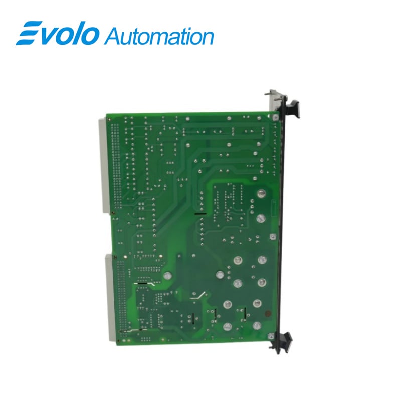
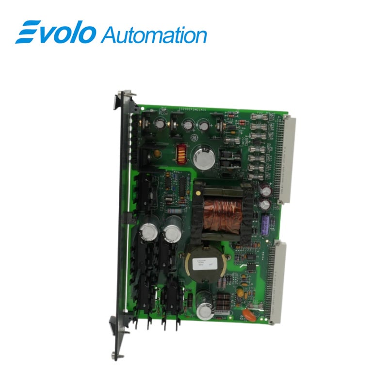
IS200EPSMG1A is an Exciter Power Supply Module developed by GE.It is a part of EX2100 turbine Control System. The EX2100 Excitation Control System and the EX2100 Regulator Control both use this Exciter Power Supply Module (EPSM). EPSM Group 1 (EPSMG1) modules are used in the excitation control system, while EPSM
Group 2 (EPSMG2) modules are used in the regulator control. The Exciter Regulator Power Supply Daughter board (EPSD) is mounted to the EPSMG2. The EPSM is made up of two major parts: a buck-regulator and a push-pull inverter.The buck-regulator converts the input voltage to an intermediate voltage of 50 V dc.This intermediate
voltage is then fed into a push-pull inverter, which generates the necessary multiple output voltages. The push-pull inverter's transformer provides high-voltage isolation between the input voltage source and the output supplied to the control system.
Features
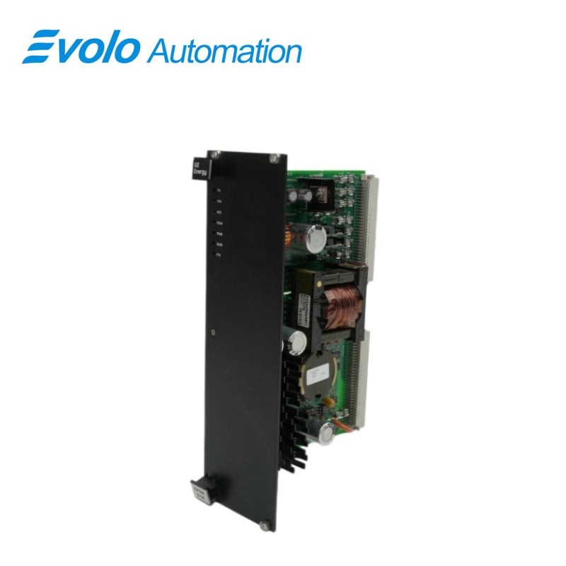
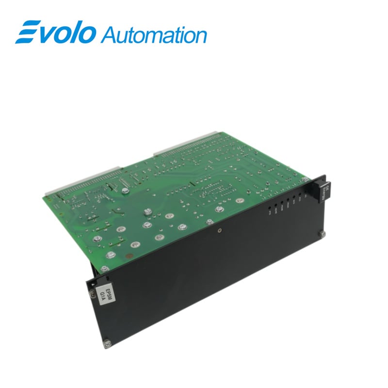
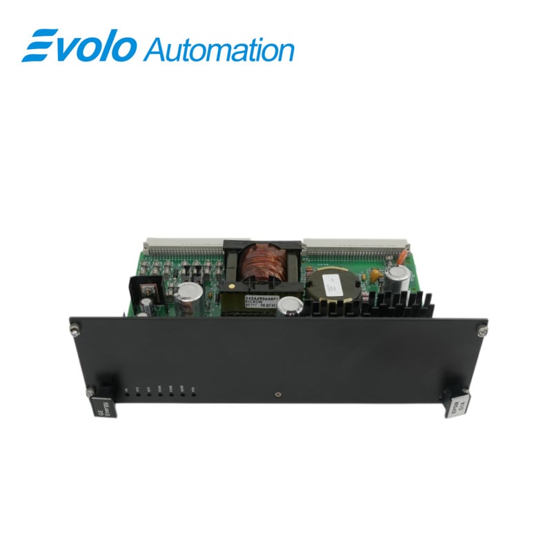
The front faceplate of the board is quite large. On the surface of this faceplate are seven LED lights. Each light has its own label. The board ID number and the manufacturer's logo are also displayed on the front panel.
The module has a transformer, a Bicron inductor (B9309 0912), a smaller inductor coil at L2, and five transistors with heat sinks. Four extra heat sink components can be found on the board in various positions
Axial electrolytic and high-voltage electrolytic capacitors are used. Other capacitors are used on the board, including a disc capacitor in the upper right quadrant. Metal film resistors and carbon composite resistors are both used.
There are nine fuses on the board. Although eight of these are packed together, the FU7 fuse is separated from the others. Integrated circuits and TP test points are also used on the board.There are also two backplane board connectors on the board.
Applications
Regulator Control Application
EPSMG2 converts the dc link bus voltage into the voltages needed to control the EX2100 regulator. One EPSMG2 is installed in the ERBPH A Exciter Regulator Backplane in simplex systems (ERBP). In redundant systems, one EPSMG2 is installed in the ERBP (M1) and another in the ERRBH A Exciter Regulator Redundant Backplane (ERRB M2/C). By increasing the creep and clearance, the EPSD mounted on EPSMG2 modifies the power input path, allowing EPSMG2 to accept higher voltages. It also acts as a fuse between the power source for the regulator (dc link) and the buck-regulator. The EPSMG2 provides the ERBP and ERRB with +5 V dc, 15 V dc, and 24 V dc. Externa modules are also powered as follows:
24 volts direct current (P24B/N24B) to power fans, relays, and the dc feedback board,
Contact-wetting isolated +70 V dc (P70) on the terminal board, dynamic discharge board, and redundant relay board,
20 V ac isolated (AC17) to power the IGBT gate and dynamic discharge board,
55 V dc (P55/N55) to the options card's ground detector circuits.
Excitation Control System Application
EPSMG1 converts 125 V dc from the power distribution module (PDM) to the voltages needed for EX2100 excitation control.Each of the controllers M1, M2, and C is powered by three independent EPSMG1s. They have installed in the control cabinet's EPBPG, A Exciter Power Backplane (EPBP), which is located beneath the EBKPG A Exciter Backplane (EBKP). Power is transferred from the EPSMG1 to the EPBP via connectors P1 and P2 for cables to the EBKP and other boards. The EPSMG1 provides power to the control assembly backplane at +5 V dc,15 V dc, and 24 V dc.External modules are also powered as follows 24 volts direct current to power the fans, de-excitation module, crowbar module,ground detector module, and field voltage/current module.
Offline Replacement
1. Ensure that the exciter has been deactivated.
2. Open the control cabinet door and ensure that the power indicators on the EPDM and EPSMG1 power supplies are not illuminated.
3. Remove the EPSMG1 from EPBP with care as follows:
1.Loosen the screws near the eiector tabs at the top and bottom of the faceplate.(The screws in the faceplate are captive and should not be removed.)
2. Remove the module by lifting the ejector tabs
3. Gently pull it from its slot in EPBP with both hands.
4. Insert the replacement EPSMG1 into the appropriate slot in the EPBP section (M1 section for simplex exciters, or M1, M2 or C section for redundant exciters).
5. Begin seating the board by firmly pressing the top and bottom of the faceplate with your thumbs at the same time
6. Finish seating the module in the slot by tightening the screws at the top and bottom of the faceplate alternately. To ensure that the module is seated squarely, tighten the screws evenly,
7. Connect power to the M1 section of the EPBP from the EPDM and ensure the EPSMG1 power indicator LEDs illuminate. Check that the green power LEDs on the M1 controller boards are also illuminated.
Online Replacement(Redundant)
It is possible to replace a failed EPSMG1 while the exciter is running in a redundant excitation control system. You can leave the failed EPsMG1 in place and run the exciter on the remaining EPSMG1s. However, if a second failure in another control section occurs, the exciter will shut down.If you want to change the EPSMG1, follow the steps below. To replace the EPSMG1 in an online redundant control system.
1. Open the control cabinet door and check the indicators on the front of the three EPSMG1 modules to confirm the failed EPSMG1. Some or all of the failed module's
green indicators will be turned off, as will the associated controller's indicators
2. Verify that control has been transferred to the other master by checking the LEDs on the IS200ESELH A Exciter Selector board (ESEL) mounted in EBKP.
3. De-energize the EPBP section containing the to-be-replaced EPSMG1. This section is de-energized by turning off the appropriate exciter power distribution module output (EPDM)
4. Verify that the LED indicator on the appropriate section of the EPDM is turned off, as well as the indicators on the EPSMG1 and corresponding controller:
5. Remove the EPSMG1 from EPBP with care as follows:
Loosen the screws near the ejector tabs at the top and bottom of the faceplate. (The screws in the faceplate are captive and should not be removed.)
Remove the module by lifting the ejector tabs.
Gently pull it from its slot with both hands.
6. Insert the replacement EPSMG1 into the appropriate slot in EPBP
7. Begin seating the board by firmly pressing the top and bottom of the faceplate with your thumbs at the same time.
8. Finish seating the module in the slot by tightening the screws at the top and bottom of the faceplate alternately. To ensure that the module is seated squarely, tighten the screws evenly,
9. Connect power to the appropriate section of the EPBP from the EPDM and ensure that the EPSMG1 power indicator LEDs illuminate. Make sure the green power LEDs on the corresponding controller boards light up.
FREQUENTLY ASKED QUESTIONS
What is IS200EPSMG1A?
IS200EPSMG1A is an Exciter Power Supply Module developed by GE under Mark VI turbine Control System
What are the main components of the IS200EPSMG1A?
The EPsM comprises two major sections: a buck-regulator and a push-pull inverter. These sections work together to regulate input voltage and generate multiple output voltages as required
What is the function of the buck-regulator about IS200EPSMG1A?
The buck-regulator is responsible for converting the input voltage to a 50 V dc intermediate voltage.This intermediate voltage serves as a crucial step in the power conversion process within the EPSM,
How does the push-pull inverter contribute to the IS200EPSMG1A's functionality?
The push-pull inverter utilizes the intermediate voltage generated by the buck-regulator to produce the reguired multiple output voltages. It operates in tandem with the buck-regulator to ensure stable and reliable power delivery to the control system.
What role does the transformer play in the push-pull inverter about IS200EPSMG1A?
The transformer employed in the push-pull inverter serves to provide high-voltage isolation between the input voltage source and the output supplied to the control system. This isolation ensures safety and prevents potential damage to the control system components.