EN
EN




- Overview
- Specifications
- Description
- Applications
- Features
- Replacement Procedures
- FAQ
- Recommended Products
Overview
Place of Origin: |
USA |
Brand Name: |
GE |
Model Number: |
IS200EGPAG1B |
Packaging Details: |
Original new Factory Sealed |
Delivery Time: |
5-7 days |
Payment Terms: |
T/T |
Supply Ability: |
In stock |
Specifications
|
Part Number: |
IS200EGPAG1B |
|
Manufacturer: |
General Electric |
|
Series: |
EX2100e |
|
Product Type: |
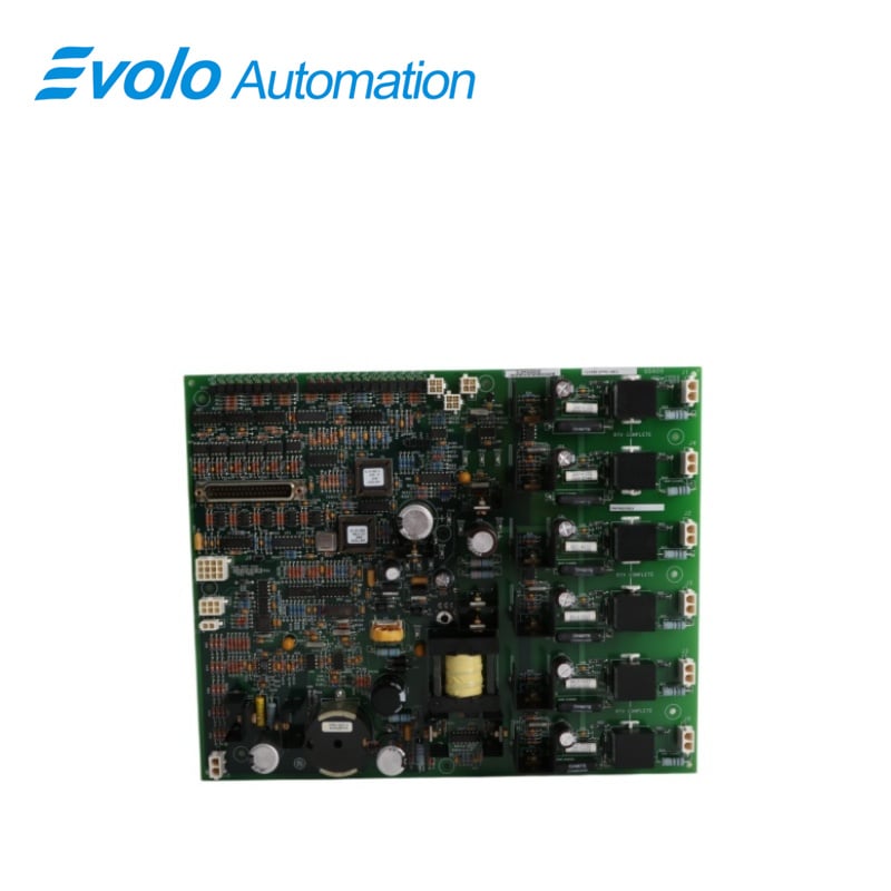
Gate Pulse Amplifier Board |
|
Instruction Manual: |
GEI-100461 |
|
LED Indicators: |
On-board Green and Red |
|
Dimensions: |
33 x 26.6 x 5 cm |
|
Weight: |
1.3 kg |
|
Country of Manufacturer: |
United States (USA) |
|
Power Supply: |
Receives 125 V DC |
|
Operating Temperature: |
-40°C to +85°C |
|
Humidity: |
5% to 95% non-condensing |
|
Vibration: |
0.05 g RMS, 57 Hz to 250 Hz |
|
Shock: |
5 g, 22 ms |
Description
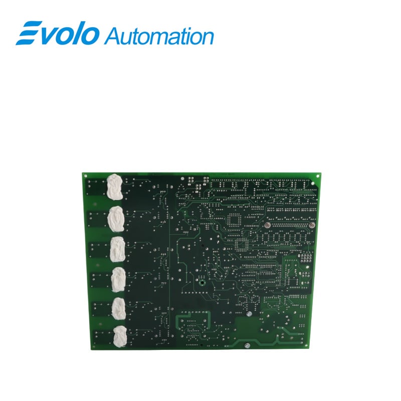
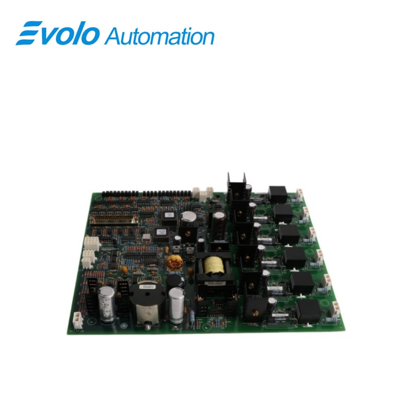
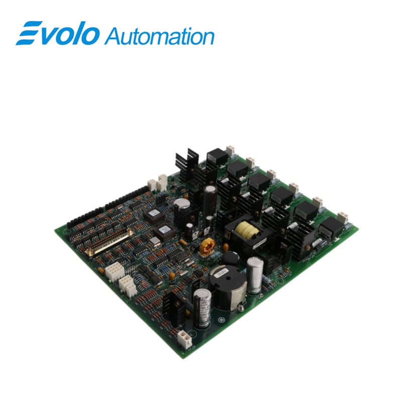
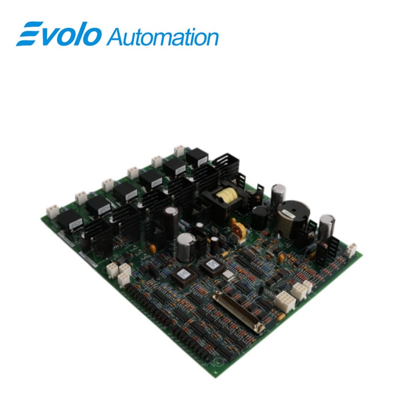
IS200EGPAG1B is a Gate Pulse Amplifier Board manufactured by General Electrics. It is a part of the EX2100e series used in gas turbine excitation system. The primary function is to manage gate commands generated by the ESEL (Excitation System Equipment List) and oversee the gate firing process for up to six SCRs (Silicon Controlled Rectifiers) situated on the Power Bridge. Additionally, the EGPA serves as the interface for various important monitoring functions, including current conduction feedback, bridge airflow, and temperature monitoring
Applications
Large power plants: GE EX2100 static excitation system for units of 300MW and above.
Synchronous motor drives: Excitation regulation for high-load motors such as those in steel mills and large compressors.
Pumped storage power stations: Supports rapid pulse response during the switching between motor and generator modes.
Features
1 Gate Control: It plays a pivotal role in controlling the gate firing process of up to six SCRs on the Power Bridge. It takes the gate commands from the ESEL and ensures the precise and timely activation of these critical components. The accurate control of the gate firing is essential for managing power flow and maintaining system stability.
2 Feedback and Monitoring: It acts as an interface for various monitoring functions, including current conduction feedback. It allows the system to keep a close eye on the electrical currents in the system, ensuring they remain within safe and desired ranges. Additionally, the EGPA is involved in monitoring bridge airflow and temperature, providing crucial data for thermal management and system safety.
3 Power Supply Management: The EGPA receives a nominal 125 V DC power supply from the EPDM (Exciter Power Distribution Module). It houses an onboard DC/DC converter, which converts this input power source into the appropriate levels needed for SCR gating. This conversion capability allows the EGPA to function consistently across a wide range of input supply voltage conditions.
4 Visual Status Indication: The board is equipped with LEDs that offer visual indications of various system statuses. These LEDs provide information regarding the status of the EGPA power supply, the reception of gate commands from the ESEL, outputs to the SCRs, currents flowing into the bridge, the performance of the line filter, the rotation of the cooling fan, bridge temperature, as well as any alarms or fault conditions. These visual indicators are essential for real-time monitoring, troubleshooting, and maintenance.
Replacement Procedures
1 De-Energize the Exciter: Ensure the exciter where the board is housed has been powered down to avoid any electrical hazards during the replacement process.
2 Electrical Circuit Test: Open the Power Conversion Cabinet door and perform thorough tests on electrical circuits to verify that power has been completely shut off before initiating any handling.
3 Check LEDs: Confirm that all LEDs are turned off to ensure no residual power or signal transmission through the board.
4 Label Verification for Cables: Ensure that each cable connected to the board is appropriately labeled with the correct connector name as indicated on the board. Proper labeling simplifies the reconnection process later on.
5 Carefully Disconnect Cables: With caution, disconnect all cables attached to the board, paying attention to avoid any damage to the connectors or the board itself.
6 Board Removal: Gently remove the board from its mounting position, ensuring a smooth extraction without causing any disturbance to nearby components.
7 Verify Replacement Board Jumpers: Prior to installation, carefully inspect the replacement card to confirm that all jumpers are correctly positioned, mirroring the configuration of the original board.
8 Install Replacement Board: Carefully re-insert the replacement board into its designated mounting slot, ensuring a proper fit and alignment.
9 Reconnect Cables: Reconnect all cables removed in the previous steps, ensuring they are appropriately reattached to their corresponding connectors on the replacement EGPA board. Securely tighten the connections to prevent any loose contacts.
FAQ
Q: What is IS200EGPAG1B?
A: It is a Gate Pulse Amplifier Board manufactured by General Electric.
Q: How are the gate commands transmitted from the ESEL to the IS200EGPAG1B EGPA?
A: The gate commands are transmitted from the ESEL to the EGPA through a twisted pair, multiconductor, shielded cable. This design helps protect the signal from interference and noise, ensuring reliable communication.
Q: What is the purpose of optically coupling the gate commands of IS200EGPAG1B?
A: Optically coupling the gate commands serves to electrically isolate the ESEL and the EGPA. It prevents electrical interference, such as voltage spikes or noise, from passing between them, which is crucial for system stability and safety.
Q: What happens to the gate commands within the IS200EGPAG1B EGPA once received?
A: Once received, the gate commands undergo filtering and AC coupling. These processes further refine the signals, ensuring that they are free from unwanted noise or distortions that could affect SCR performance.
Q: How does the EGPA interface with the IS200EGPAG1B Gate Pulse Amplifiers (GPA)?
A: EGPA serves as an intermediary, sending the processed and refined gate commands to the Gate Pulse Amplifiers (GPA). The GPA, in turn, is responsible for controlling the SCR operation.
Q: What additional functions does the IS200EGPAG1B EGPA serve apart from SCR control?
A: In addition to SCR control, it acts as an interface for various functionalities such as current conduction feedback and monitoring bridge airflow and temperature, contributing to efficient operation and monitoring of the system.
Q: What key features are depicted in the functional model of IS200EGPAG1B?
A: The functional model highlights major I/O (Input/Output) elements critical to its operation and monitoring. This model helps visualize the connectivity and interactions within the EGPA.
Q: How does the IS200EGPAG1B manage its power supply for SCR gating?
A: It incorporates an on-board DC/DC converter powered by a nominal 125 V DC source from the EPDM. This converter enables SCR gating across a full range of input supply voltage.
Q: What visual indicators does the component offer of IS200EGPAG1B?
A: LEDs provide visual indications of various statuses, including the power supply, input gate commands from ESEL, EGPA outputs to the SCRs, currents into the bridge, line filter conditions, cooling fan rotation, bridge temperature, alarms, or fault conditions.