EN
EN




- Overview
- Specifications
- Description
- Board Mounting
- Application Data
- Characteristics
- FREQUENTLY ASKED QUESTIONS
- Recommended Products
Overview
Place of Origin: |
USA |
Brand Name: |
GE |
Model Number: |
DS215SLCCG1AZZ01B DS200SLCCG1AEG |
Packaging Details: |
Original new Factory Sealed |
Delivery Time: |
5-7 days |
Payment Terms: |
T/T |
Supply Ability: |
In stock |
Specifications
|
Part Number: |
DS215SLCCG1AZZ01B, DS200SLCCG1AEG |
|
Manufacturer: |
General Electric |
|
Series: |
EX2000 |
|
Product Type: |
LAN Communications Card |
|
Number of Relay Channels: |
12 |
|
Operating System: |
QNX |
|
Power Supply Voltage: |
24 V dc |
|
Mounting: |
DIN-rail mounting |
|
Technology: |
Surface mount |
|
Operating Temperature: |
40 to 70 °C |
|
Dimensions: |
18.8 x 14.3 x 2 cm |
|
Weight: |
0.26 kg |
|
Country of Manufacturer: |
United States (USA) |
Description
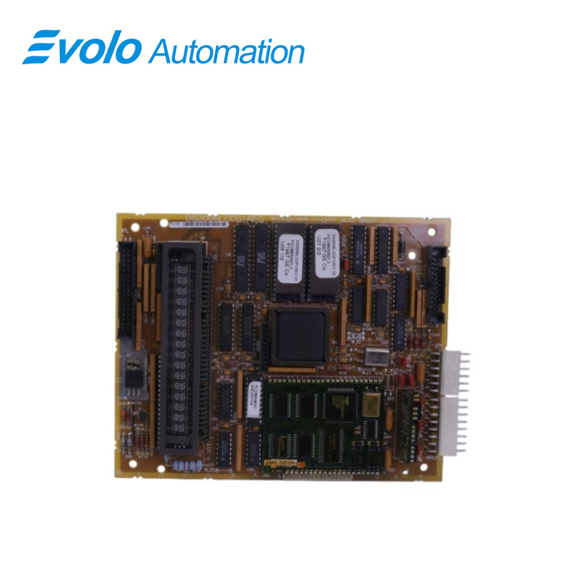
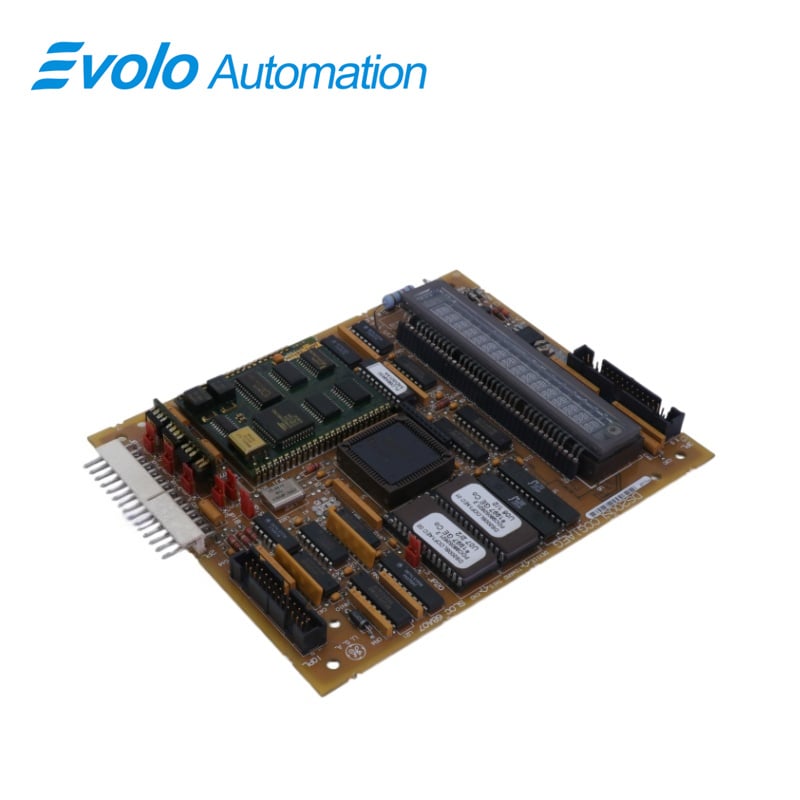
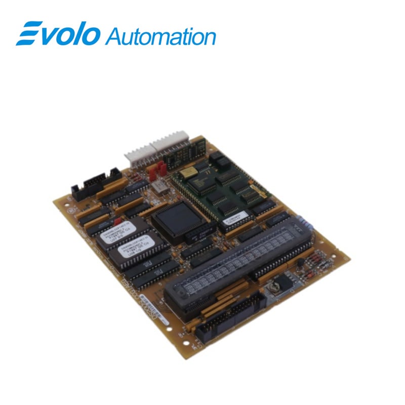
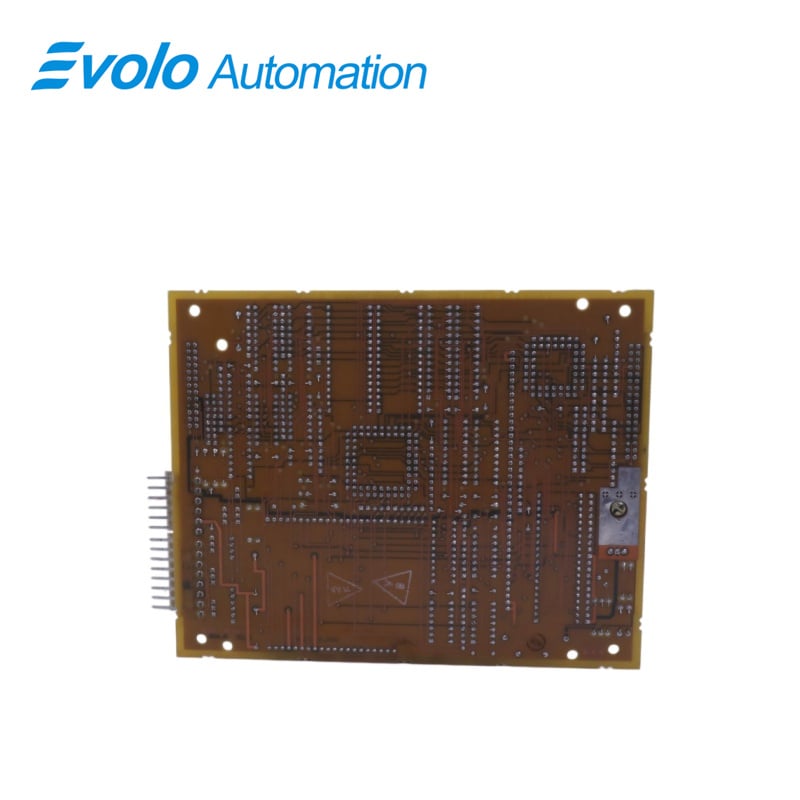
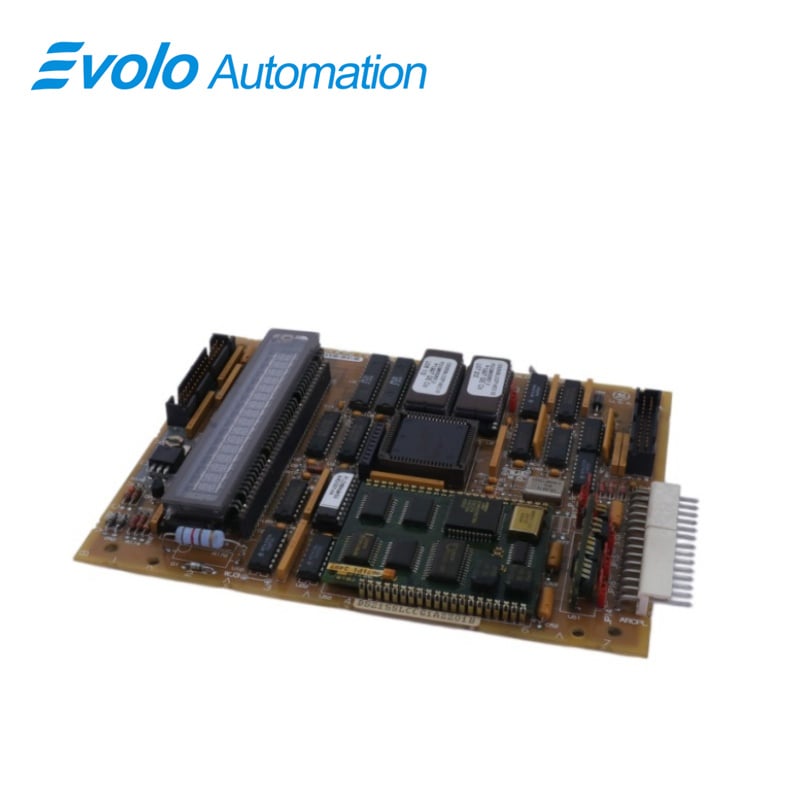
DS215SLCCG1AZZ01B DS200SLCCG1AEG is a LAN Communications Card developed by GE. It is a part of the Mark V control system. It has circuits for communications with the drive or exciter that are both isolated and non-isolated. The programmer module is connected to the 16-position alphanumeric display (and display controller, U18). The KPPL connector receives the programmer module, which is mounted to the SLCC. The LAN Control Processor, U1, is the main microprocessor (LCP). Two replaceable EPROMs contain the LCP software (U6 and U7). U8 and U9 supply the LCP-specific memory. Communication between the LCP and the Drive Control Processor (DCP) on the Drive Control Card occurs via 3PL and dual-ported RAM (U5). Dual-ported RAM [DPR] is RAM set up as memory arrays that two microprocessors may access both independently and concurrently. Mark V improves unit reliability even further by employing three redundant control processors. This triple modular redundant (TMR) design can safely operate, control, and protect a unit in the event that one of its control processors or control processor components fails. The TMR design allows for the shutdown and repair of a single control processor without shutting down the turbine.
Board Mounting
1.Features four standoffs that serve as mounting points. Standoffs are small supports or spacers that elevate and secure the board in a fixed position. These standoffs provide stability and ensure proper alignment between the module and the surrounding components or enclosure.
2.Includes a connector labeled KPPL, which is designed to accept a programmer module plug. The programmer module plug is a specific type of connector that allows for communication and interaction. When the programmer module plug is connected to the KPPL connector, it establishes a physical and electrical connection between the LAN Card and the programmer module.
3.Covered by the keypad and cover module. This module is specifically designed to provide a protective enclosure and to house the keypad interface. The keypad allows users to input commands, configurations, or other instructions, facilitating control and interaction with the module. The cover module is shielded from external elements and provides a secure housing for the keypad and other components.
Application Data
Includes configurable hardware that must be set correctly for the application:
1.Berg-type Hardware Jumpers: The configurable hardware includes Berg-type hardware jumpers, which are identifiable by the JP nomenclature. These jumpers are physical connectors that can be manually adjusted or moved to establish or break connections on the device. The JP nomenclature provides a standardized way of labeling and identifying these jumpers.
2.Wire Jumpers: In addition to the hardware jumpers, the device also utilizes wire jumpers, which are identified by the WJ nomenclature. Wire jumpers consist of physical wires that are used to create connections between specific points on the device. Similar to hardware jumpers, wire jumpers offer flexibility in configuring the device's circuitry.
Characteristics
1.Critical Communication: Turbine control systems require highly reliable and low-latency communication to ensure the safe and efficient operation of the turbine. LAN Communications Cards are specifically engineered to meet these stringent communication requirements.
2.Redundancy: Redundancy is often a critical feature in turbine control systems to ensure continued operation even in the event of hardware failures. LAN Communications Cards may support features like dual NlCs (Network Interface Cards) or redundant network paths to enhance system reliability.
3.Industrial-Grade: Turbine control environments can be harsh, with factors like temperature variations, vibrations, and electromagnetic interference. LAN Communications Cards used in such systems are typically built to withstand these harsh conditions and are designed to be rugged and durable.
4.Protocol Support: Turbine control systems may use specific communication protocols or standards. LAN Communications Cards are designed to support these protocols, ensuring seamless integration with the control system and other devices on the network.
5.Security: Security is a paramount concern in critical systems like turbine control. These cards may include security features such as hardware encryption, firewall capabilities, and support for secure communication protocols to protect against unauthorized access or tampering
6.Monitoring and Diagnostics: Advanced LAN Communications Cards for turbine control systems often include diagnostic and monitoring features. These features allow for real-time monitoring of network performance and card health, aiding in the early detection of issues.
7.Integration with SCADA Systems:Turbine control systems are often part of larger Supervisory Control and Data Acquisition (SCADA) systems. LAN Communications Cards facilitate the seamless integration of turbine data into the SCADA network, allowing for centralized monitoring and control.
FREQUENTLY ASKED QUESTIONS
Q: What is DS215SLCCG1AZZ01B DS200SLCCG1AEG?
A: It is a LAN Communications Card developed by GE.
Q: What is the main microprocessor on the DS215SLCCG1AZZ01B DS200SLCCG1AEG?
A: The main microprocessor on the board is the LAN Control Processor (LCP), which is located on U1. The LCP communicates with the Drive Control Processor (DCP) on the Drive Control Card via 3PL and dual-ported RAM (U5).
Q: What should be done when ordering replacement DS215SLCCG1AZZ01B DS200SLCCG1AEG that require the EPROMs U6 and U7?
A: When ordering replacement boards that require the EPROMs U6 and U7, the EPROMs from the old board must be transferred to the new board.
Q: What should be specified of DS215SLCCG1AZZ01B DS200SLCCG1AEG when replacing an SLCC (or LCC) and the EPROMs are required?
A: When replacing an SLCC (or LCC) and the EPROMs are required, a SLCC should be specified to ensure that both EPROMs are included.
Q: How is the programmer module connected to this DS215SLCCG1AZZ01B DS200SLCCG1AEG LAN Communications Card, and what does it control?
A: The programmer module is connected to the card via the KPPL connector. It interfaces with the 16-position alphanumeric display and display controller and plays a key role in controlling and configuring the LAN Communications Card.
Q: What is the LAN Control Processor (LCP), and what are its main components of DS215SLCCG1AZZ01B DS200SLCCG1AEG?
A: The LAN Control Processor (LCP), represented by U1, serves as the main microprocessor. It is equipped with replaceable EPROMs (U6 and U7) and specific memory components (U8 and U9) that house the LCP software and data.
Q: How does communication occur between the LCP and the Drive Control Processor (DCP)?
A: Communication between the LCP and the DCP on the Drive Control Card is facilitated through 3PL and dual-ported RAM (U5). Dual-ported RAM allows two microprocessors to access memory independently and concurrently.
Q: What is the significance of the triple modular redundant (TMR) design of DS215SLCCG1AZZ01B DS200SLCCG1AEG in the Mark V control system?
A: The TMR design enhances unit reliability by employing three redundant control processors. In the event of a control processor failure, the system can safely continue to operate, control, and protect the unit without shutdown, ensuring uninterrupted performance.