EN
EN




- Overview
- Specifications
- Description
- Applications
- FEATURE
- FREQUENTLY ASKED QUESTIONS
- Recommended Products
Overview
Place of Origin: |
USA |
Brand Name: |
GE |
Model Number: |
DS200TCCAG1BAA |
Packaging Details: |
Original new Factory Sealed |
Delivery Time: |
5-7 days |
Payment Terms: |
T/T |
Supply Ability: |
In stock |
Specifications
|
Part Number: |
DS200TCCAG1BAA |
|
Manufacturer: |
General Electric |
|
Series: |
Mark V |
|
Product Type: |
TC2000 Common Analog I/O Board |
|
Mounting Location: |
R5 Core |
|
Communication Connector: |
3PL |
|
Input Signal Types: |
4-20 mA |
|
Output Signal Type: |
4-20 mA |
|
Output Connectors: |
JAA |
|
Weight: |
0.45 kg |
|
Dimensions: |
28 x 18 cm |
|
Country of Origin: |
United States |
Description
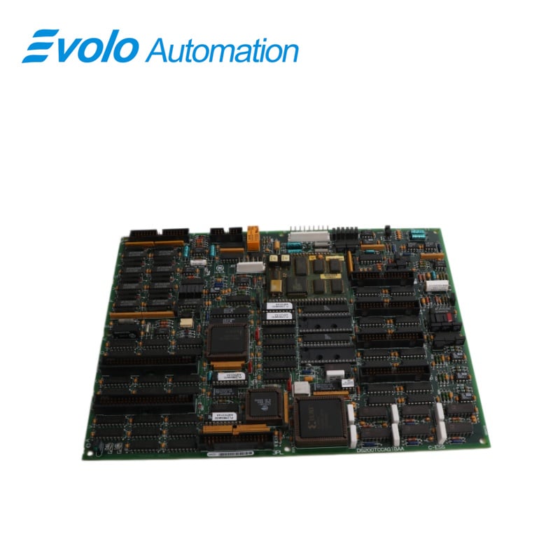
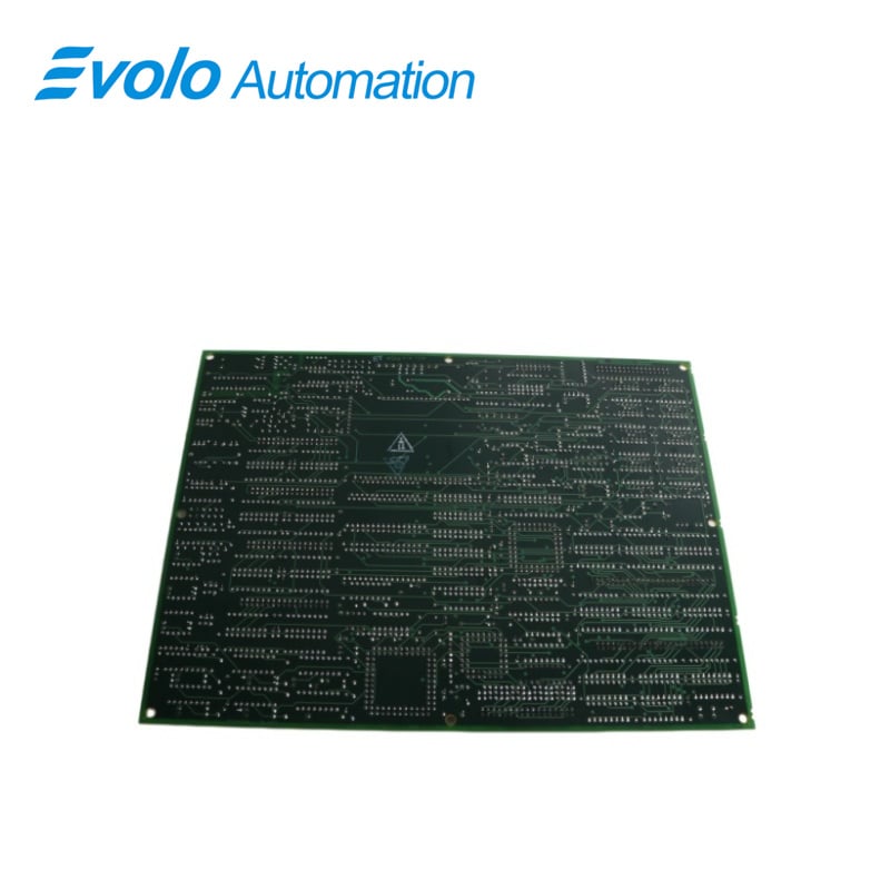
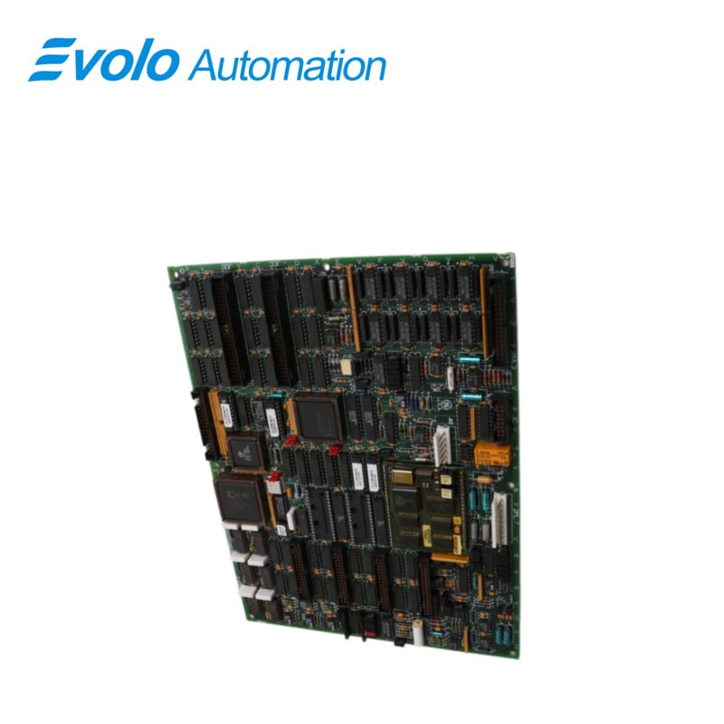
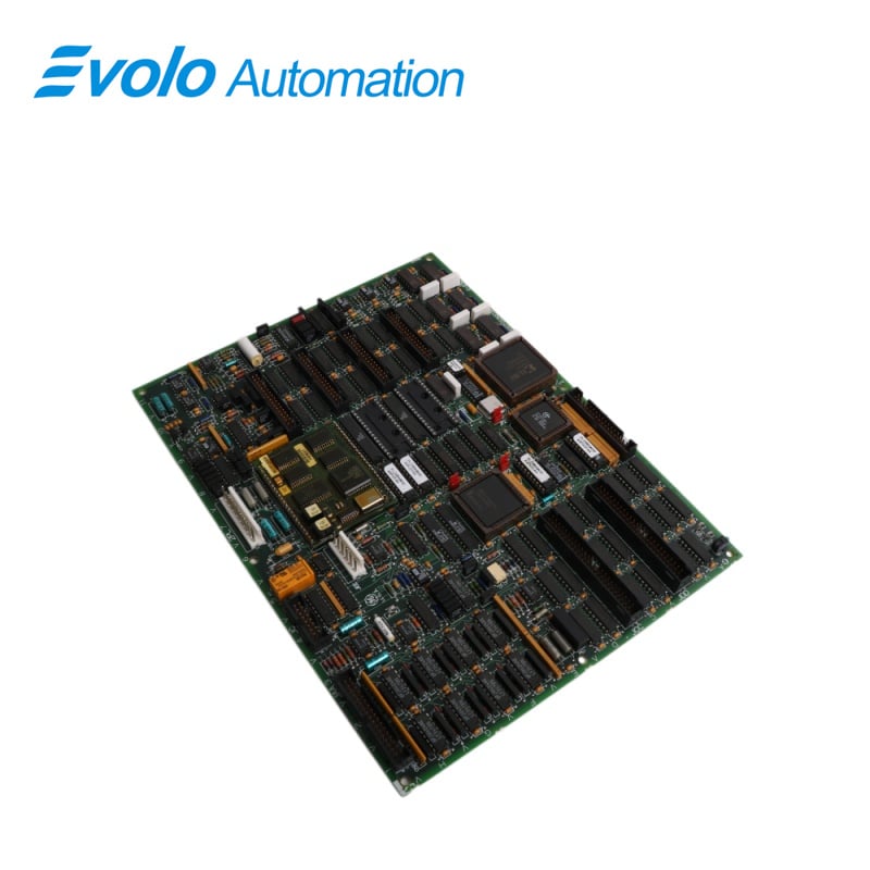
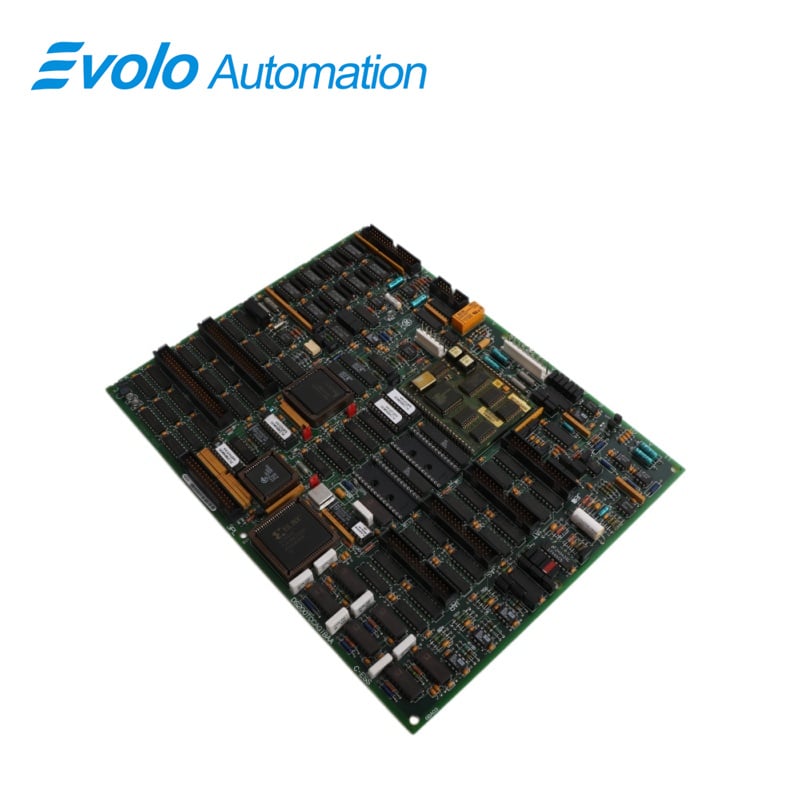
DS200TCCAG1BAA is a TC2000 Common Analog I/O Board manufactured and designed by General Electric as part of the Mark V Series used in GE Speedtronic Gas Turbine Control Systems. The Common Analog I/O Board (TCCA), located in the core, scales and conditions analog signals from the CTBA, TBOA, and TBCA terminal boards mounted in the core. These signals include 4-20 mA inputs and outputs, RTD inputs, thermocouple inputs, shaft voltage inputs, and shaft current inputs. The signals are written to the STCA board via the 3PL connector.
Applications
Energy and Power Plants:
Gas Turbine Control: Standard configuration for GE Mark V control systems, used in Frame 6, 7, and 9 series gas turbines.
Core Monitoring: Real-time acquisition and processing of analog data such as exhaust temperature, bearing vibration, and speed.
Oil & Gas and Petrochemical Plants:
Power Drive Systems: Used for automated management of compressor stations, pump stations, and large centrifuges.
Explosion-proof and Safety Control: Processes 4-20 mA sensor signals to ensure stable operation of chemical plant production lines.
Heavy Manufacturing and Paper/Steel Mills:
Distributed Control Systems (DCS): Serves as the central hub for analog signal processing in self-contained power plants or complex drive systems in large plants.
FEATURE
1.TCCA CONFIGURATION:
Hardware: The TCCA board has three hardware jumpers n J1, JP2, and JP3.J1 is used to enable/disable the serial RS232 port.JP2 disables the oscillator for card test.JP3 is used for factory testing Software: I/O configuration constants for the thermocouples, RTDs, mA inputs and outputs, and the shaft voltage and current settings are entered in the I/O Configuration Editor located on the HMI as described below.
2.TCCA 4-20 mA INPUT CIRCUIT
The TCCA board provides the circuitry for the 4-20 mA input signals. The signals are read from the CTBA terminal board via the JBB connector. The transducer current is dropped across a burden resistor, and the voltage drop is read by the TCCA board and written to the I/O Engine via the 3PL connector.
3.TCCA 4-20 mAINPUT CIRCUIT
The TCCA board provides the circuitry for driving 4-20 mA outputs to the CTBA terminal board via the JAA connector. These signals are typically used to drive remote instrumentation for monitoring.
4.TCCA TRD CIRCUIT
The circuitry that supplies excitation to the RTDs from the TBCA terminal board is located on the TCCA board. A steady current is sent through the RTD, and when the temperature changes, the resistance changes, causing the voltage on the RTD to change.The TCCA board measures, scales, and conditions the voltage signal.The RTDsignals are read from the TBCA terminal board by the TCCA board over the JCC and JDD connectors.The TCCA board sends the signals to the I/O Engine via the 3PL connector.The type of RTD is selected using I/O configuration constants.
5.TCCA THERMOCOUPLE CIRCUIT
The TBOA terminal board reads the thermocouple inputs. The cold junction circuitry on the TBOA terminal board provides the cold junction signals. The TCCA board uses these values to calculate the cold junction compensation. The TCCcA board uses the thermocouple input and compensation value to calculate the actual temperature read by the thermocouple. The lI/O Engine reads the value via the 3PL connector. Thermocouple types and curves are selected using I/O configuration constants.
6.TCCA SHAFT MONITORING:
The monitoring for the turbine shaft voltage and current is provided by the TCCA board. These signals are read from the CTBA terminal board via the JBB connector. The signals are written to the I/O Engine via the 3PL connector.
FREQUENTLY ASKED QUESTIONS
Q: How does the DS200TCCAG1BAA manage signal conditioning from multiple terminal boards within the core?
A: The DS200TCCAG1BAA (TCCA board) gathers analog input signals from multiple terminal boards such as CTBA, TBOA, and TBCA within the system core. It performs signal conditioning on these inputs—including current loops, RTDs, and thermocouples—by filtering, amplifying, and converting them into standardized formats. This ensures that all signals are uniform and suitable for accurate processing and communication with the control system.
Q: What role does the 3PL connector play in system communication for the DS200TCCAG1BAA?
A: The 3PL connector serves as the main communication interface between the TCCA board and the I/O Engine. It transmits all conditioned analog signals from the board, enabling reliable, real-time data exchange for monitoring and control operations within the system.
Q: Why is jumper JP2 important during DS200TCCAG1BAA testing procedures?
A: Jumper JP2 is used to disable the onboard oscillator, which is essential during certain diagnostic or factory-level testing procedures. By disabling the oscillator, engineers can isolate specific functions of the board and perform accurate troubleshooting or validation without interference from normal operating signals.
Q: How does the DS200TCCAG1BAA differentiate and handle various RTD types during operation?
A: The DS200TCCAG1BAA distinguishes different RTD types through predefined I/O configuration constants in the control system. It applies a fixed excitation current to the RTD and measures the resulting voltage changes caused by resistance variations. These measurements are then scaled and interpreted based on the selected RTD type, ensuring precise temperature monitoring across different sensor configurations.