EN
EN




- Overview
- Specifications
- Description
- Applications
- Other details
- Replacement Procedure
- Frequently Asked Questions
- Recommended Products
Overview
Place of Origin: |
USA |
Brand Name: |
GE |
Model Number: |
DS200RTBAG3AEB |
Packaging Details: |
Original new Factory Sealed |
Delivery Time: |
5-7 days |
Payment Terms: |
T/T |
Supply Ability: |
In stock |
Specifications
|
Part Number: |
DS200RTBAG3AEB |
|
Manufacturer: |
General Electric |
|
Country of Manufacture: |
United States of America (USA) |
|
Temperature: |
0 to 60 °C |
|
Product Type: |
Relay Terminal Module |
|
Dimensions: |
28.8 x 7.2 x 3.7 cm |
|
Weight: |
0.38 kg |
|
Series: |
EX2000 |
|
Relays: |
10 relays |
|
Relay Types: |
7 DPDT relays, 3 4PDT relays |
|
Activation: |
Direct from LAN I/O Terminal Board or remote |
|
I/O Connectors: |
16-pin RPL, 2-pin OPTPL, jumper selectable signals |
|
Control Power Connectors: |
CPH (hot), CPN (negative), jumper selectable |
|
Pluggable Circuits Access: |
C1PL–C5PL, Y9PL–Y37PL, jumper selectable |
|
Relay I/O Terminals: |
1–52, jumper selectable |
|
Two-Conductor Plugs: |
CP1PL–CP5PL, Y9PL–Y37PL, release lever |
|
Board Removal: |
Remove 4 screws with washers, lift carefully |
|
Cable Reconnection: |
Reconnect all cables, ensure proper seating |
|
Wire Reconnection: |
Reconnect individual labeled wires securely |
Description
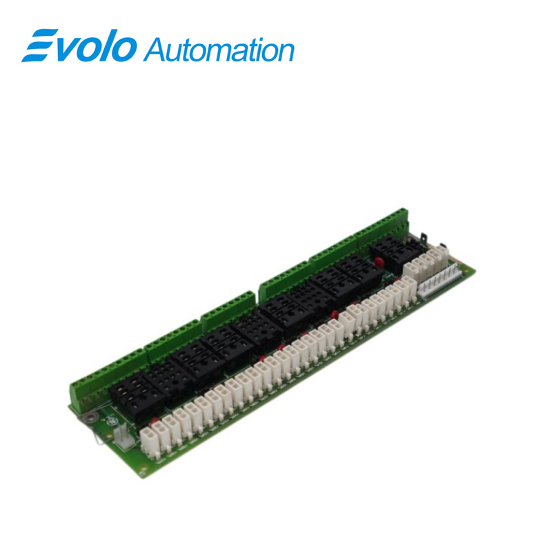
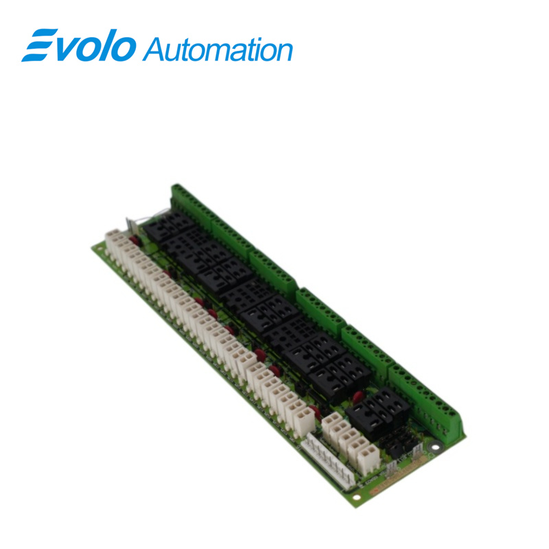
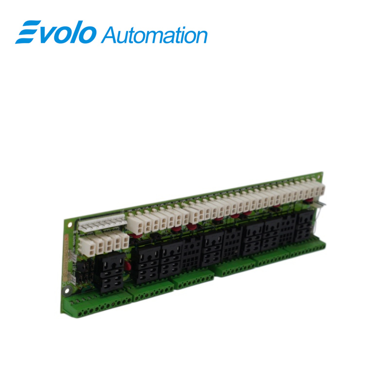
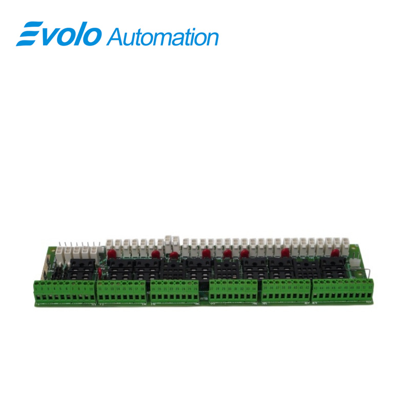
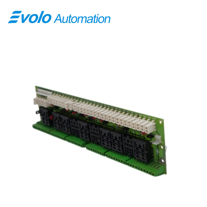
DS200RTBAG3AEB is a Relay Terminal Module developed by GE.It is a part of EX2000 excitation system.It is an optional board located within the drive (or exciter) cabinet.The board offers ten relays that can be activated either directly from the pilot relays on the LAN I/O Terminal Board (LTB) or remotely by the user.Among these, seven relays are equipped with two Form C contacts, known as DPDT relays, while the remaining three relays feature four Form C contacts each.
Applications
Power Industry:
Turbine Control: Integrated into the GE Mark V system for driving auxiliary equipment (such as oil pumps and fans) of gas turbines or steam turbines.
Generator Excitation: Handles critical interlock protection logic and circuit breaker trip signals in the EX2000 system.
Heavy Industrial Plants:
Signal Isolation: Protects vulnerable microprocessor control circuits (low voltage) from surges caused by high-power motors or solenoid valves (high-voltage/inductive loads) in the field.
Remote Control Interface: Allows operators to remotely switch the operating status of field equipment from the control room.
Other details
1.I/O Connectors with LTBA Board: The RTBA board establishes crucial communication with the LTBA board through two primary connectors: a 16-pin connector labeled RPL and a 2-pin connector named OPTPL. These connectors serve as conduits for Input/Output (I/O), facilitating the exchange of signals and data between the two boards. It's noteworthy that certain signals on the RPL connector are designated as jumper selectable, offering users the flexibility to configure these signals based on specific operational requirements.
2.Control Power Stab Connectors: To supply control power to designated pluggable circuits, the RTBA board features two stab connectors, namely CPH (control power hot, positive) and CPN (control power negative). The functionality of these stab connectors is not fixed but rather jumper selectable, allowing users to tailor the control power source to align with the specific needs of the pluggable circuits.
3.Pluggable Circuits and Relay Access: The RTBA board provides accessibility to pluggable circuits and relays K27 to K29 through distinct connectors. Pluggable circuits are accessible via connectors C1PL to C5PL and Y9PL to Y37PL. These connectors serve as entry points for external connections and additional peripherals, enriching the RTBA board's capabilities. Importantly, the control power source for these pluggable circuits is also jumper selectable, adding another layer of adaptability for users to configure as per their requirements.
4.Relay I/O Connections: For the I/O connections between the RTBA board relays K20 to K26 and external signals, the board is equipped with terminals numbered 1 to 52. These terminals serve as interface points for relays, enabling external signals to be seamlessly integrated with the RTBA board. Similar to other features, the control power source for these relays is jumper selectable, allowing users to customize the power source configuration based on the specific needs of their application.
Replacement Procedure
1.Power Off and Safety Precautions: Turn off the power to the drive and allow several minutes for capacitors to discharge. Test electrical circuits before any handling to ensure complete power shutdown.
2.Accessing the RTBA Board: Open the drive's cabinet door to access the RTBA board, typically located below the drive's board rack.
3.Cable Disconnection: Carefully disconnect all cables from the RTBA board: For ribbon cables, gently pull the cable connector loose by grasping each side. For cables with pull tabs, carefully pull the tab. For wires attached to RTB terminals, loosen the screw at the top of each terminal and pull each wire free. Ensure wires are labeled for easy reconnection.
4.Two-conductor plugs (CP1PL-CP5PL and Y9PL-Y37PL) feature integral holding clips; press the connector lever to release the connector.
5.Removing the RTBA Board: Remove the four screws with washers securing the RTBA board to the four standoffs. Lift the board carefully, ensuring not to drop mounting hardware into the unit to prevent damage.
6.Configurable Item Alignment: Set all configurable items on the replacement (new) board in the exact position as those on the board being replaced (old board).
7.Installing the New Board: Install the new board onto the four standoffs using the four screws and washers removed in step 5.
8.Cable Reconnection: Reconnect all cables disconnected in step 3, ensuring each connector is properly seated at both ends.
9.Individual Wire Reconnection: Reconnect all individual wires that were disconnected in step 3 (as labeled), ensuring each wire is properly secured in the terminal.
Frequently Asked Questions
Q: What is DS200RTBAG3AEB?
A: It is a Relay Terminal Module developed by General Electric under the EX2000 series.
Q: Is the control power source for the pluggable circuits configurable on DS200RTBAG3AEB?
A: Yes, the control power source for the pluggable circuits is jumper selectable. This feature allows users to choose and configure the appropriate control power source for the pluggable circuits based on the specific needs of their application.
Q: Are there any precautions to consider when configuring jumpers or replacing connectors on the DS200RTBAG3AEB?
A: Yes, to prevent equipment damage and ensure safety, it is important to follow proper procedures when configuring jumpers or replacing connectors. Refer to the user manual or documentation provided with the board for specific guidelines, and always perform these tasks with the system power turned off.