EN
EN




- Overview
- Specifications
- Description
- Applications
- Physical Installation
- Repair and Replacement
- FAQ
- Recommended Products
Overview
Place of Origin: |
Sweden |
Brand Name: |
ABB |
Model Number: |
SPDSO14 |
Packaging Details: |
Original new Factory Sealed |
Delivery Time: |
5-7 days |
Payment Terms: |
T/T |
Supply Ability: |
In stock |
Specifications
|
Model: |
SPDSO14 |
|
Type: |
DO Module |
|
Channel Type: |
DO |
|
Number of Output Channels: |
16 |
|
Dimensions (D x H x W): |
73.66 x 360.68 x 279.4 mm |
|
Output Type: |
Open Collector, optically isolated |
|
Operating Voltage: |
+5V DC ±5% |
|
Operating Current: |
275 mA typical, 370 mA maximum |
|
Power Dissipation: |
1.4 W typical, 1.9 W maximum |
|
Load Voltage: |
24 VDC at 150 mA typical, 250 mA maximum; 48 VDC at 75 mA typical, 125 mA maximum |
|
Off Leakage Current: |
10 µA at 70°C maximum |
|
On Voltage Drop: |
2 V at 70°C maximum |
|
Common Mode Isolation: |
300 VDC VRMS at 60 Hz |
|
Tested Withstand Voltage: |
1,400 V for 2 s at 60 Hz |
|
Mounting: |
Occupies one slot in standard module mounting unit |
|
Overvoltage Category: |
I for power, II for outputs |
|
Ambient Temperature: |
0°C to 70°C |
|
Relative Humidity: |
5%–95% up to 55°C (non-condensing); 5%–45% at 70°C (non-condensing) |
|
Pollution Degree: |
1 |
|
Altitude: |
Sea level to 3 km |
|
Air Quality: |
Noncorrosive |
|
ESD Protection: |
Contact ±6 kV, Air ±8 kV (IEC 61000-4-2) |
|
Magnetic Fields: |
Power frequency: Continuous 30 A/m, Short duration 300 A/m; Pulse: 300 A/m peak; Damped oscillatory: 30 A/m peak, 0.1–1 MHz |
|
Radiated RF: |
10 V/m RMS unmodulated, 80% AM (1 kHz), 80 MHz–1 GHz |
|
Additional RF Tests: |
900 ±5 MHz, pulse modulated 50% duty, 200 Hz repeat cycle |
|
Radio-Frequency Common Mode: |
10 V/m RMS, 80% AM (1 kHz), 0.15–80 MHz |
|
Emission Class: |
Class A (30 MHz – 1000 MHz) |
|
WEEE Category: |
5. Small Equipment (No External Dimension More Than 50 cm) |
|
Number of Batteries: |
0 |
Description
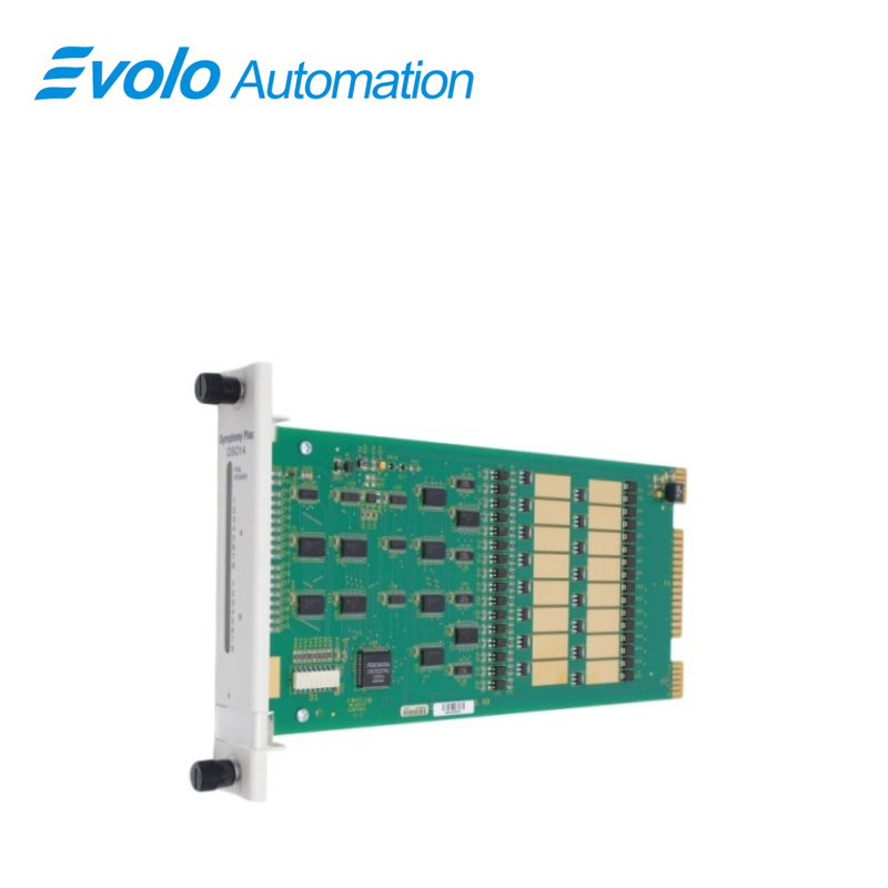
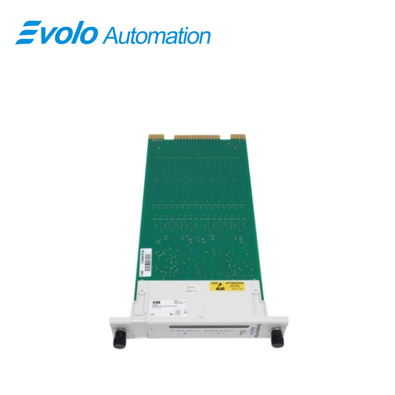
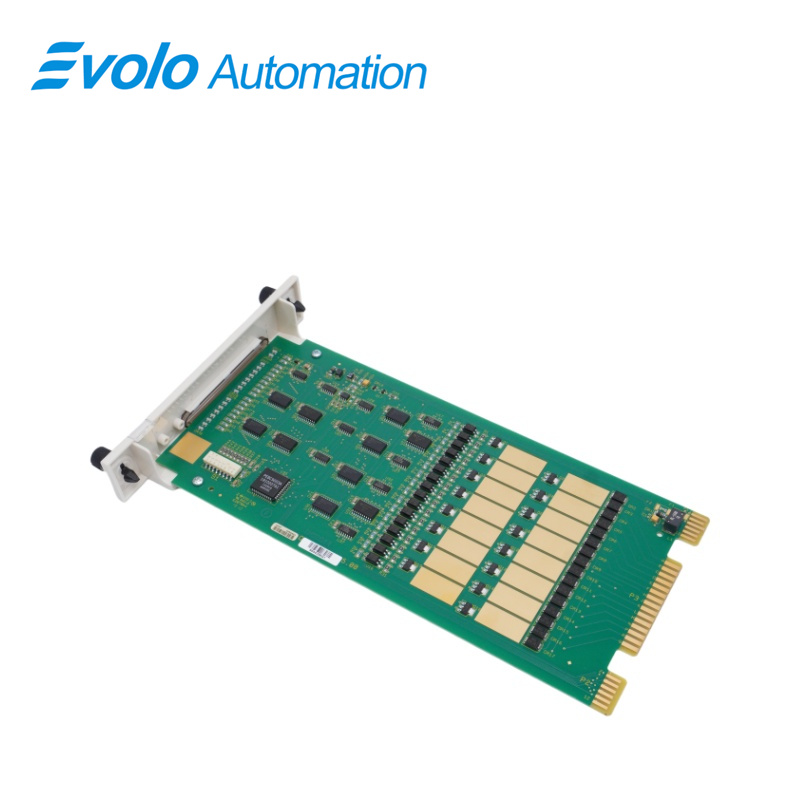
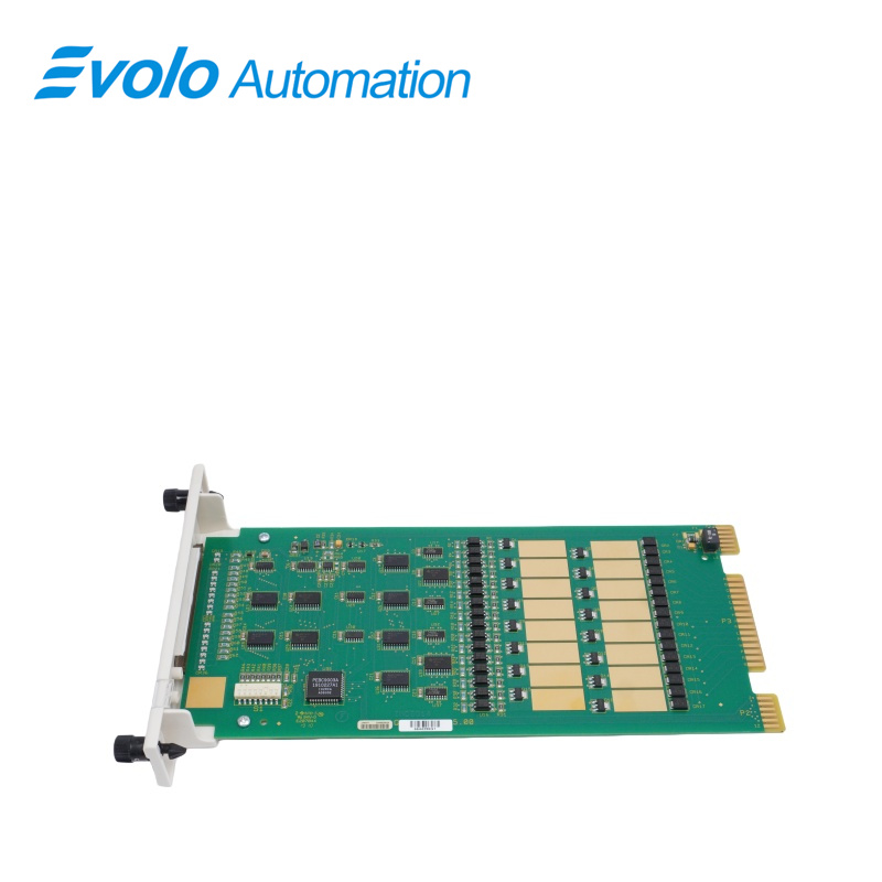
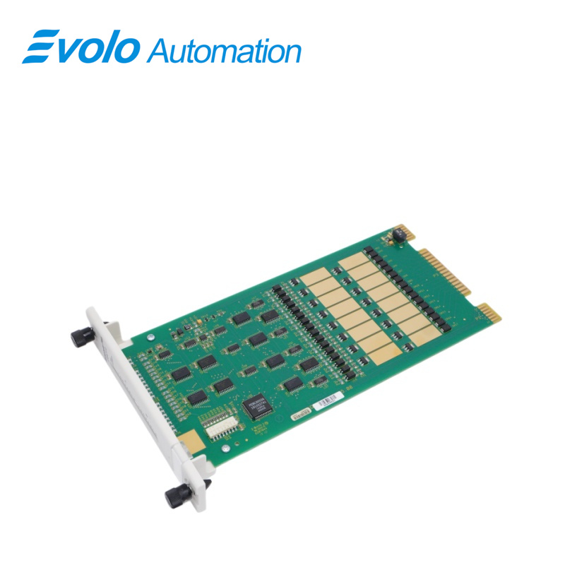
The SPDSO14 Digital Output Module is a Harmony rack I/O module that replaces the Bailey Hartmann & Braun system with ABB Symphony Enterprise Management and Control System. It has 16 open-collector, digital output channels that can switch 24 and 48 VDC load voltages. The digital outputs are used by the controller to switch field devices for process control. Two captive screws on the faceplate secure the DSO14 module to the module mounting unit. The upper two front panel red and green LEDs indicate the module operating status. The 16 lower front panel red LEDs (group A and group B) display the module output states (on or off).
Applications
Chemical Plant: Drives emergency shut-off valves (ESD) and agitator start/stop relays.
Thermal Power Plant: Controls contactor closing for auxiliary machine motors and activation of audible and visual alarms.
Steel Plant: Regulates the operation of hydraulic station solenoid valves and controls conveyor line sorting levers.
Cement Plant: Controls the hoist braking system and feeder start/stop switches.
Pharmaceutical Plant: Links cleanroom fans and reactor feed solenoid valves.
Physical Installation
The DSO module inserts into a standard module mounting unit (MMU) and occupies one slot. To install
1. Verify the slot assignment of the module.
2. Verify that a dipshunt is in the I/O expander bus socket on the module mounting unit's backplane between the I/O module and controller. Disconnect power before installing dipshunts on the MMU backplane. Failure to do so will result in contact with cabinet areas that could cause severe or fatal shock.
3.For termination units, connect the hooded end of the termination cable from the termination unit to the module mounting unit backplane. To do this, insert the connector into the backplane slot in the same slot as the one assigned to the digital output module. The latches should snap securely into place.
4. Align the digital output module with the guide rails in the module mounting unit. Gently slide the module in until the front panel is flush with the top and bottom of the module mounting unit frame.
5.Push and turn the two captive retaining screws on the module faceplate one half turn to the latched position. It is latched when the slots on the screws are vertical and the open ends face the center of the module.
Repair and Replacement
If the DsO module is faulty, replace it with a new one. Do not try to repair the module; replacing components may affect the module performance. System power may remain applied during module removal and replacement.
To replace a module:
1.Push and turn the two front panel captive retaining screws one-half turn to unlatch the module.
NOTE: It is unlatched when the slots on the screws are vertical and the open end of the slots face away from the module.
2. Slide the module gently out of the module mounting unit.
3. Configure the replacement module switch settings. Insure they are set the same as the original module.
4. Align the replacement module with the guide rails in the module mounting unit in the same slot assignment as the original module.
5. Slide it gently in until the front panel is flush with the top and bottom of the MMU frame.
6. Push and turn the two captive retaining screws on the module faceplate one half turn to the latched position.
NOTE: It is latched when the slots on the screws are vertical and the open ends face the center of the module.
7. Return to normaloperation.
FAQ
Q: Can the SPDSO14 directly drive an AC 220V load?
A: No, it cannot be directly connected. The SPDSO14 provides low-level outputs and must be used with a relay output terminal unit (such as NTDO02) for proper load switching.
Q: What is the difference between the SPDSO14 and the SPDSO04?
A: The SPDSO14 is an upgraded version, offering improved response speed, enhanced diagnostics, and better compatibility with newer controllers.
Q: Are the output channels of the SPDSO14 isolated?
A: The internal logic and output stages are opto-isolated, but the 16 output channels typically share a common reference ground.
Q: How can I confirm if a channel of the SPDSO14 is outputting?
A: The front panel includes LEDs labeled 1–16. A green LED indicates that the corresponding channel output logic is active (“1” state).
Q: Can a faulty SPDSO14 module be replaced while powered on?
A: Yes. The module supports hot-swapping. In redundant systems or non-critical applications, it can be replaced without shutting down the system.