EN




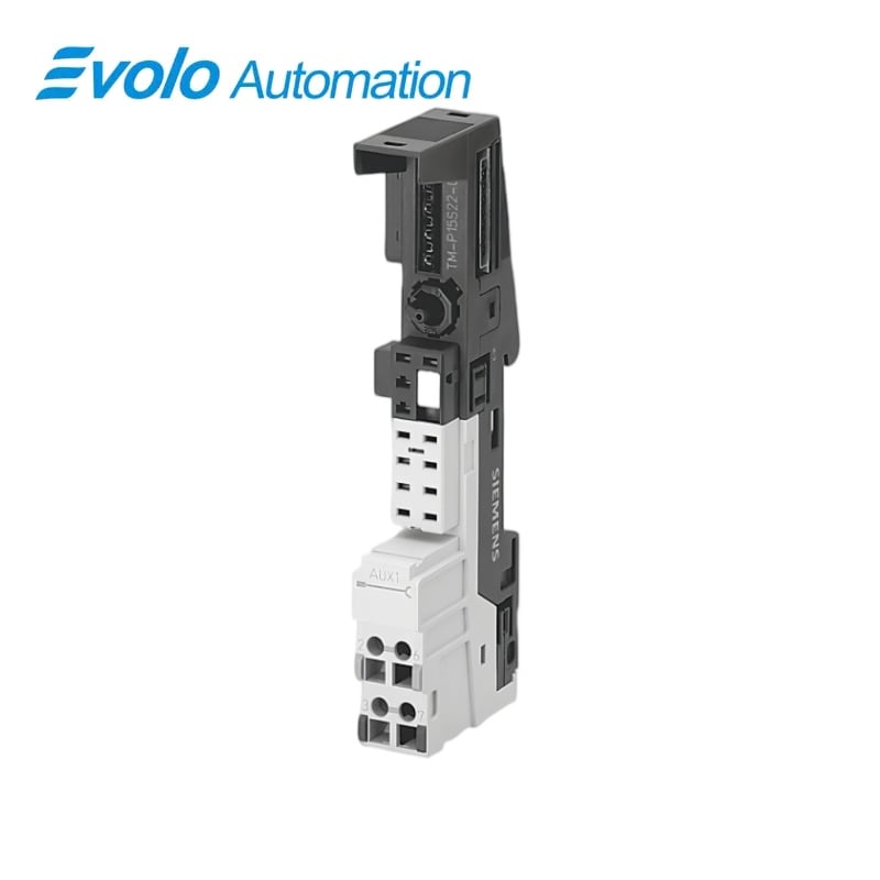
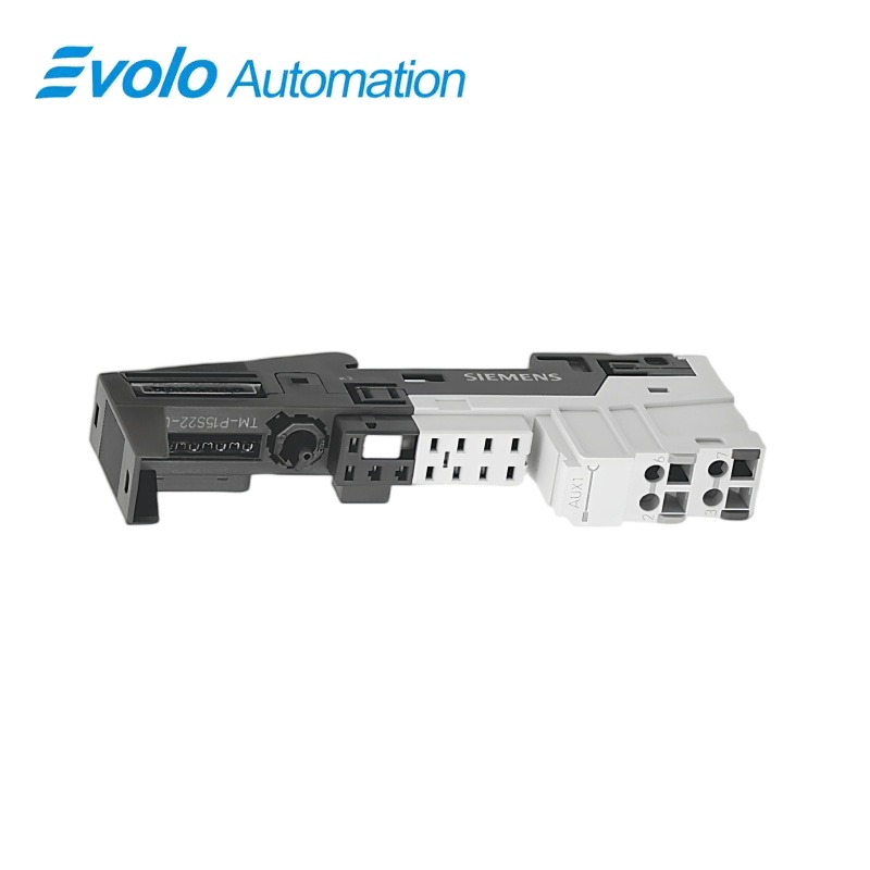
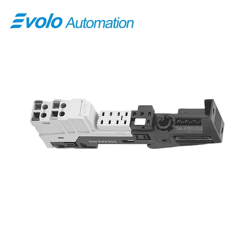
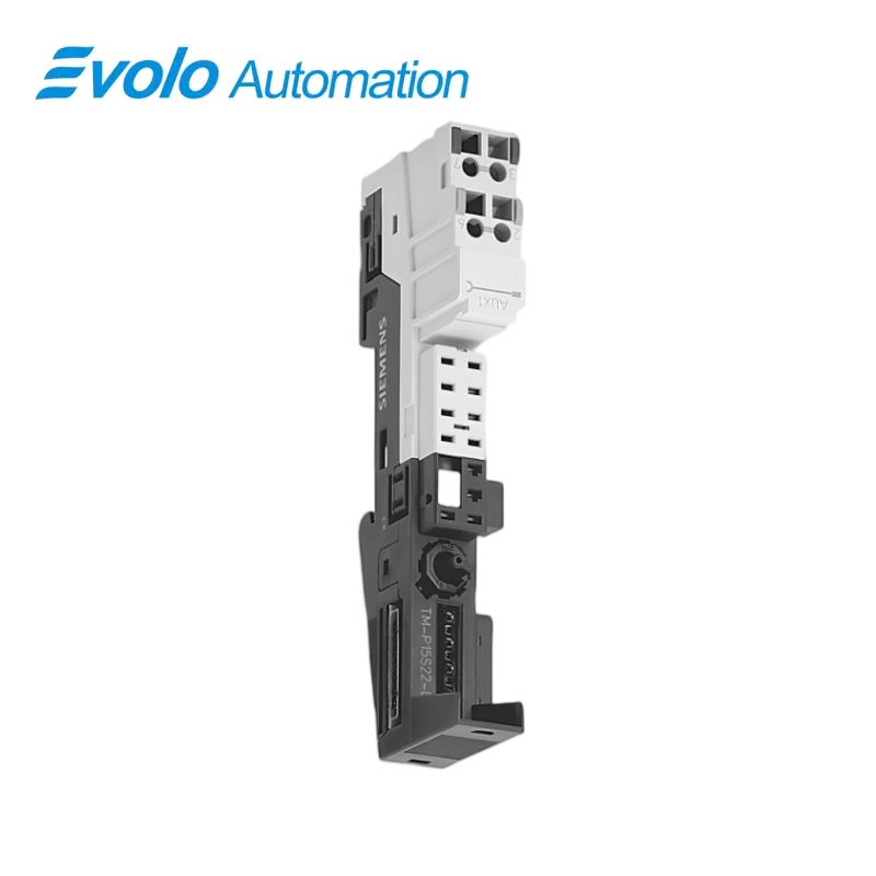
Siemens 6ES7193-4CE00-0AA0 SIMATIC ET 200S TM-P15S22-01 Terminal Module
Manufacturer: Siemens
Condition: Brand New
Lead Time: In Stock
Origin: Germany
Warranty: 12 Months
Email: [email protected]
whatsApp: +86-18150117685
- Overview
- Hot Selling Models
- Recommended Products
Overview
- Plan the potential group boundary at the TM-P position.
- Match the power module to the four-connection base.
- Retain AUX1 continuity to the neighboring group on the left.
- Prepare 11 mm stripped ends and apply 0.4–0.7 N·m torque.
SIEMENS SIMATIC ET 200S
6ES7193-4CE00-0AA0 SIMATIC ET 200S TM-P15S22-01 Terminal Module
A four-connection screw-terminal base for ET 200S power modules, with AUX1 continuity and no local auxiliary terminal.
At a Glance
| Brand | Siemens |
|---|---|
| Model | 6ES7193-4CE00-0AA0 |
| Product Type | Power module base |
| Core Function | Potential group infeed |
| Application | ET 200S power distribution |
New supply group
The installed power module feeds a new potential group extending to the next TM-P base.
Four screw connections
The compact 2 × 2 layout provides the power-module connection positions without an AUX1 terminal row.
119.5 mm height
A 15 × 119.5 × 43 mm body fits this reduced terminal arrangement.
Product Overview
6ES7193-4CE00-0AA0 provides the TM-P15S22-01 screw-terminal mounting and wiring base for a SIMATIC ET 200S power module.
It starts a new power potential group while the separate AUX1 bus remains electrically connected to the group on the left, with no terminal access at this position.
Key Functions
Establish the next power section
The power-module base introduces the supply for electronic modules up to the next TM-P in the station.
Pass AUX1 without a local tap
The continuous auxiliary bus travels through the base without connecting to external terminals.
Terminate four supply wires
The 2 × 2 screw connections support conventional stripped field conductors with specified torque control.
Official Specifications
| Terminal arrangement | 2 × 2 connections |
|---|---|
| Connection technology | Screw terminals |
| AUX1 routing | Continuous to the potential group on the left |
| AUX1 terminal access | No terminal access |
| Bare solid and flexible conductor range | 0.14–2.5 mm² |
| Flexible conductor range with ferrule | 0.14–1.5 mm² |
| Wire stripping length | 11 mm |
| Conductors per connection | 1; alternatively 2 totaling up to 1.5 mm² in a shared ferrule |
| Maximum wire insulation diameter | 3.1 mm at 1.5 mm²; 3.8 mm at 2.5 mm² |
| Wiring tool | Screwdriver with 3 mm blade |
| Terminal tightening torque | 0.4–0.7 N·m |
| Dimensions (W × H × D) | 15 × 119.5 × 43 mm |
| Approximate module weight | 55 g |
Frequently Asked Questions
Can 6ES7193-4CE00-0AA0 begin a separate ET 200S power potential group?
Yes, it provides the infeed base for a new group that extends to the next TM-P terminal module.
Does 6ES7193-4CE00-0AA0 support Four screw connections for mobile equipment?
No, the AUX1 bus remains continuous across that group boundary.
Can I land a protective conductor directly on 6ES7193-4CE00-0AA0?
This variant has no AUX1 terminal access, so a local protective-conductor connection through AUX1 requires a suitable different base.
Is 6ES7193-4CE00-0AA0 the compact four-connection version?
Yes, its screw-terminal layout has two pairs of connections and an overall height of 119.5 mm.
What changes when I add ferrules to wires for 6ES7193-4CE00-0AA0?
The permitted flexible-wire cross-section becomes 0.14–1.5 mm² with ferrules instead of the 0.14–2.5 mm² bare-wire range.
How many 6ES7193-4CE00-0AA0 bases should I count per delivery unit?
The exact order number supplies one terminal module per delivery unit.
How do I latch 6ES7193-4CE00-0AA0 into the station row?
Fit the base to the DIN rail, lock it backward onto the rail and slide it left until it snaps into the preceding module.