EN




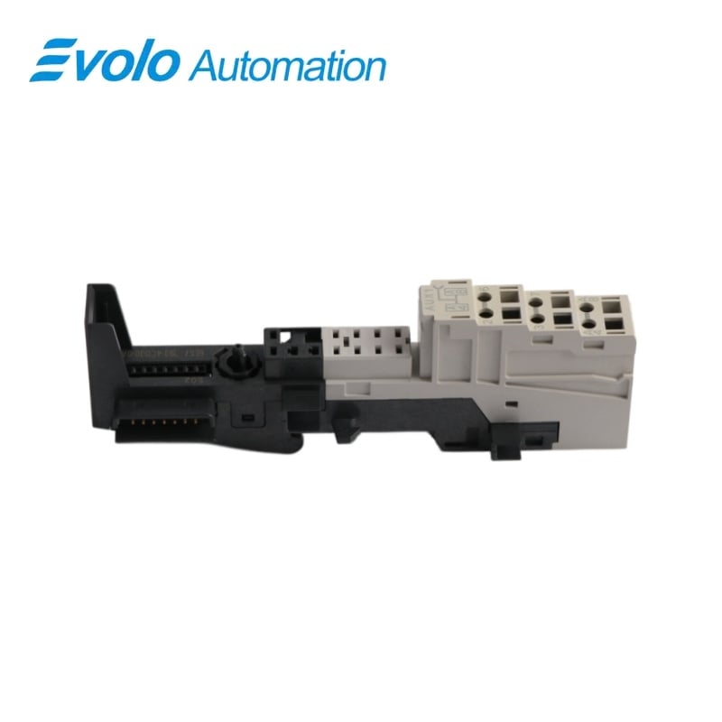
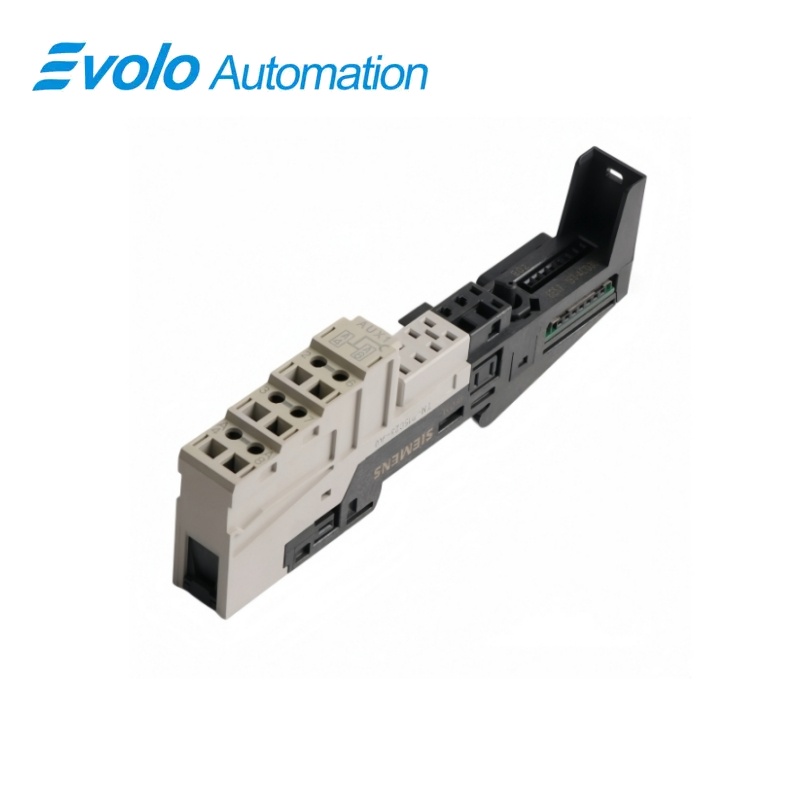
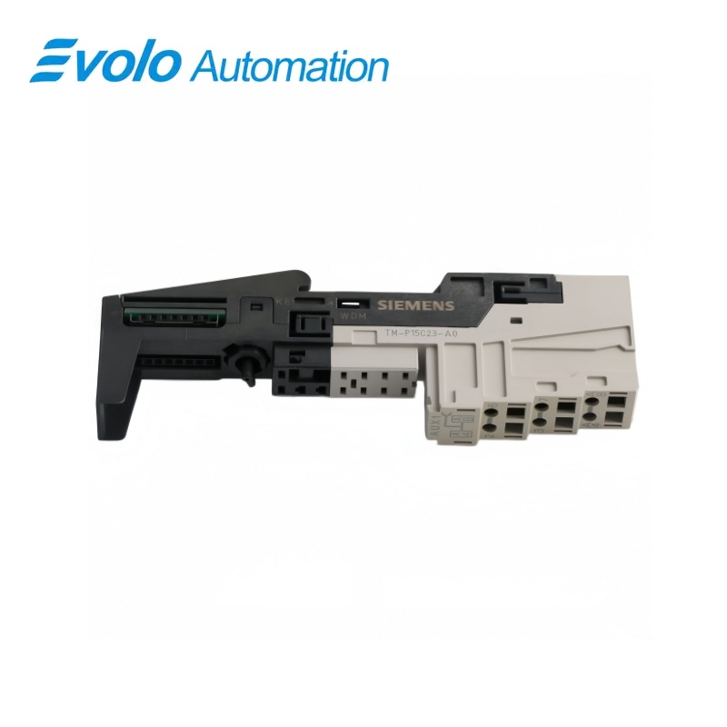
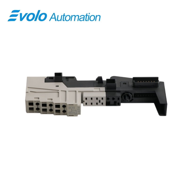
Siemens 6ES7193-4CD30-0AA0 SIMATIC ET 200S TM-P15C23-A0 Terminal Module
Manufacturer: Siemens
Condition: Brand New
Lead Time: In Stock
Origin: Germany
Warranty: 12 Months
Email: [email protected]
whatsApp: +86-18150117685
- Overview
- Hot Selling Models
- Recommended Products
Overview
- Keep the -A0 interrupted AUX1 topology in the replacement plan.
- Provide the required local auxiliary feed at A4 and A8.
- Match the power module and 2 × 3 spring-terminal layout.
- Strip 11 mm and open each spring clamp with a 3 mm screwdriver.
SIEMENS SIMATIC ET 200S
6ES7193-4CD30-0AA0 SIMATIC ET 200S TM-P15C23-A0 Terminal Module
A spring-terminal power-module base with local AUX1 connections and an interrupted auxiliary bus at the left-hand group boundary.
At a Glance
| Brand | Siemens |
|---|---|
| Model | 6ES7193-4CD30-0AA0 |
| Product Type | Power module base |
| Core Function | Potential group infeed |
| Application | ET 200S power distribution |
AUX1 group separation
The -A0 version interrupts the auxiliary bus to the potential group on the left.
Accessible auxiliary feed
A4 and A8 give the new section its own AUX1 connection points.
Spring-clamp wiring
Six terminal positions use Cage Clamp connections operated with a 3 mm screwdriver.
Product Overview
6ES7193-4CD30-0AA0 is the TM-P15C23-A0 spring-terminal base for an ET 200S power module and a separately fed AUX1 section.
The base combines a new power potential group with an interrupted AUX1 boundary, allowing the auxiliary feed on A4 and A8 to be defined for the local group.
Key Functions
Separate the auxiliary section
The AUX1 bus has no electrical continuation to the potential group on the left.
Introduce the required AUX1 potential
Terminals A4 and A8 connect the local auxiliary bus as a protective-conductor or application potential connection.
Build the power-module station position
The TM-P base receives the power module and feeds the electronic-module power buses to the next TM-P boundary.
Official Specifications
| Terminal arrangement | 2 × 3 connections |
|---|---|
| Connection technology | Spring terminals (Cage Clamp) |
| AUX1 routing | Interrupted at the boundary to the potential group on the left |
| AUX1 terminal access | A4 and A8 |
| Bare solid and flexible conductor range | 0.14–2.5 mm² |
| Flexible conductor range with ferrule | 0.14–1.5 mm² |
| Wire stripping length | 11 mm |
| Conductors per connection | 1; alternatively 2 totaling up to 1.5 mm² in a shared ferrule |
| Maximum wire insulation diameter | 3.1 mm at 1.5 mm²; 3.8 mm at 2.5 mm² |
| Wiring tool | Screwdriver with 3 mm blade |
| Dimensions (W × H × D) | 15 × 132 × 43 mm |
| Approximate module weight | 65 g |
Frequently Asked Questions
What happens to the upstream AUX1 supply at 6ES7193-4CD30-0AA0?
The interrupted -A0 bus prevents AUX1 from continuing electrically from the potential group on the left.
Does 6ES7193-4CD30-0AA0 support Accessible auxiliary feed for mobile equipment?
Use A4 and A8 to connect the auxiliary potential for this group.
Can 6ES7193-4CD30-0AA0 keep power-group and auxiliary-group boundaries together?
Yes, the power-module base starts a new power group while its interrupted AUX1 bus also separates the auxiliary section from the left-hand group.
Do I need to torque the spring connections on 6ES7193-4CD30-0AA0?
No screw tightening is used for the Cage Clamp terminals, which are opened with a 3 mm screwdriver to insert the prepared wire.
Can I use AUX1 on 6ES7193-4CD30-0AA0 for an additional AC potential?
The auxiliary bus can carry an application potential up to 230 V AC when the station is designed and wired for that use.
Is 6ES7193-4CD30-0AA0 lower than the four-terminal TM-P version?
No, this six-connection version is 132 mm high compared with 119.5 mm for the four-connection TM-P15C22-01.
How should I remove the wired base 6ES7193-4CD30-0AA0 during service?
Switch off the relevant supply, disconnect its wiring and create approximately 8 mm clearance before releasing the base from the rail.