EN





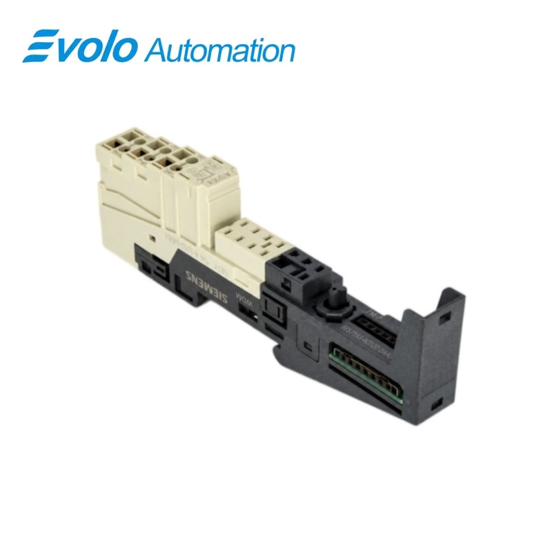
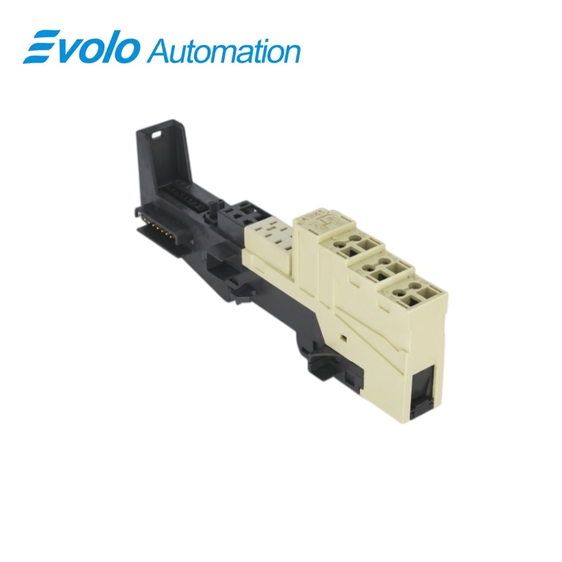
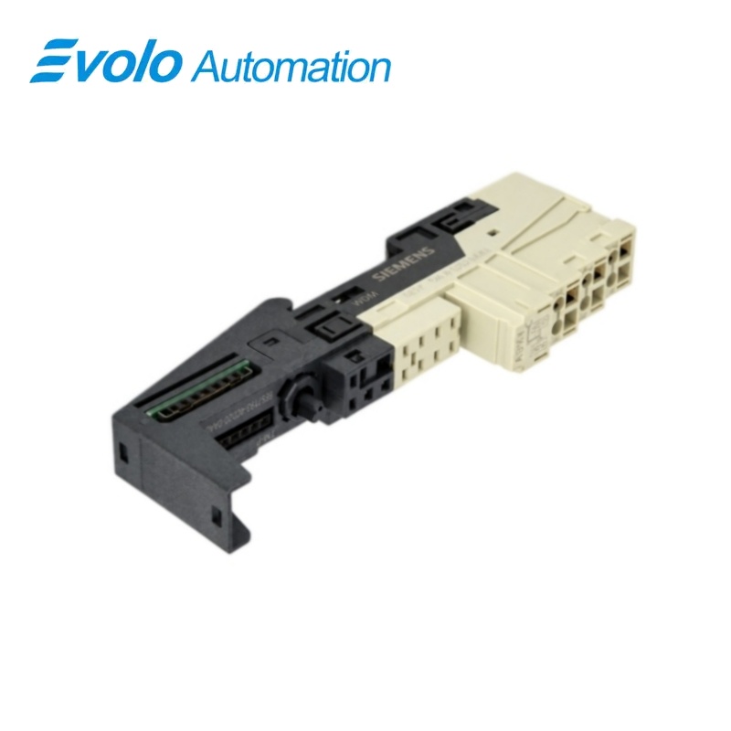
Siemens 6ES7193-4CD20-0AA0 SIMATIC ET 200S TM-P15S23-A0 Power Terminal Module
Manufacturer: Siemens
Condition: Brand New
Lead Time: In Stock
Origin: Germany
Warranty: 12 Months
Email: [email protected]
whatsApp: +86-18150117685
- Overview
- Hot Selling Models
- Recommended Products
Overview
- Retain AUX1 separation from the left-hand group.
- Match the PM-E type and its required supply.
- Strip 11 mm and apply the specified screw torque.
- Use the 132 mm housing height in cabinet planning.
6ES7193-4CD20-0AA0 SIMATIC ET 200S TM-P15S23-A0 Power Terminal Module
A screw-terminal power base that starts a new load-potential group and interrupts AUX1 from the preceding group.
At a Glance
| Brand | Siemens |
|---|---|
| Model | 6ES7193-4CD20-0AA0 |
| Product Type | Power module terminal base |
| Core Function | Separate auxiliary-potential infeed |
| Application | ET 200S PM-E power modules |
Independent AUX1 infeed
The auxiliary bus is interrupted toward the potential group on the left.
Accessible auxiliary points
Terminals A4 and A8 provide the local AUX1 connection.
New power group
The inserted power module feeds downstream electronic modules up to the next TM-P base.
Product Overview
6ES7193-4CD20-0AA0 provides the screw-terminal foundation for an ET 200S power module where a separate auxiliary potential is needed.
Its A0 construction breaks AUX1 continuity to the preceding group, while the local auxiliary terminals provide the new infeed connection.
Key Functions
Start a separately supplied group
The power module on the base supplies the following electronic modules until the next power-terminal boundary.
Separate the auxiliary bus
The interrupted AUX1 path prevents an electrical connection to the adjacent potential group on the left.
Make screw-terminal field connections
The removable terminal arrangement accepts bare or ferruled conductors within the ET 200S wiring limits.
Official Specifications
| Connection technology | Screw terminals |
|---|---|
| Terminal arrangement | 2 × 3 connections |
| AUX1 landing positions | A4 and A8 |
| Auxiliary bus routing | Interrupted toward the potential group on the left |
| Bare solid and flexible conductor range | 0.14–2.5 mm² |
| Flexible conductor range with ferrule | 0.14–1.5 mm² |
| Wire stripping length | 11 mm |
| Conductors per terminal | 1; alternatively 2 totaling up to 1.5 mm² in a shared ferrule |
| Maximum wire insulation diameter | 3.1 mm at 1.5 mm²; 3.8 mm at 2.5 mm² |
| Terminal tightening torque | 0.4–0.7 N·m |
| Dimensions (W × H × D) | 15 × 132 × 43 mm |
| Approximate module weight | 65 g |
Frequently Asked Questions
Will 6ES7193-4CD20-0AA0 carry AUX1 through from the preceding power group?
No, the A0 design interrupts AUX1 toward the preceding potential group.
Where do I feed the new auxiliary potential on 6ES7193-4CD20-0AA0?
The local auxiliary bus is accessible through terminals A4 and A8.
Can 6ES7193-4CD20-0AA0 be used below the PM-E DC24V module 6ES7138-4CA01-0AA0?
Yes, the TM-P15S23-A0 is a compatible screw-terminal base for that power module.
How far does the load-potential group started at 6ES7193-4CD20-0AA0 extend?
It extends through the following electronic-module bases up to the next TM-P terminal module.
What tightening torque should I use on 6ES7193-4CD20-0AA0?
Tighten the terminal screws to 0.4–0.7 N·m using a screwdriver with a 3 mm blade.
Can two field wires share one connection on 6ES7193-4CD20-0AA0?
Two conductors may share a terminal when combined in a common ferrule with a total cross-section no greater than 1.5 mm².
How much space should I allow vertically for 6ES7193-4CD20-0AA0?
The screw-terminal housing is 132 mm high, so the installation must accommodate that height and its wiring access.