EN
EN




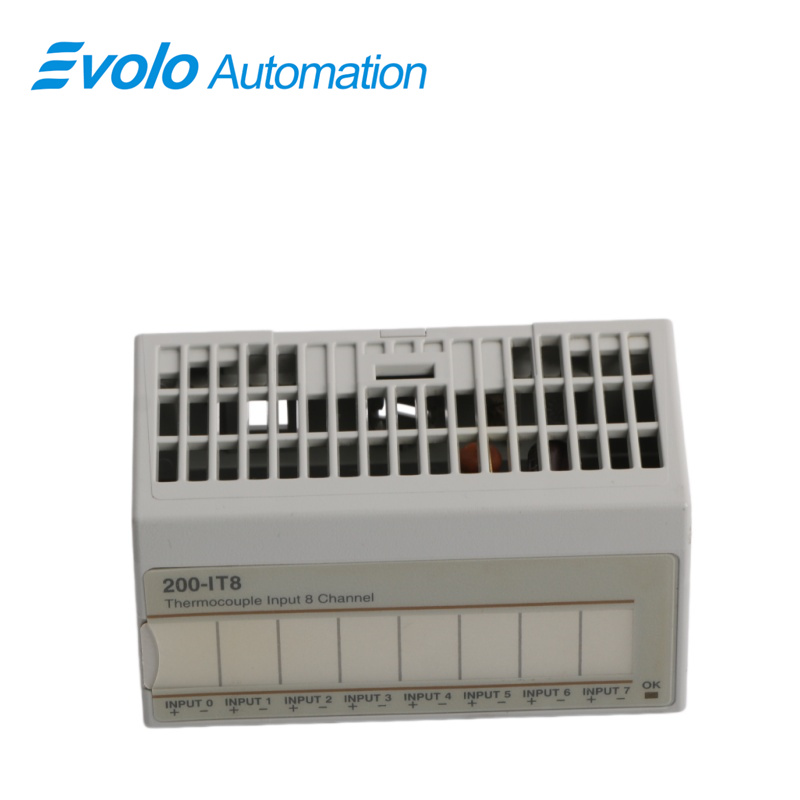
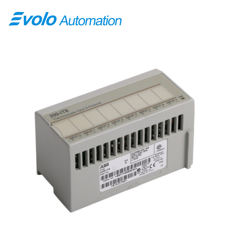
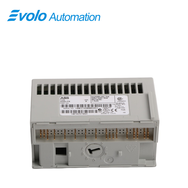
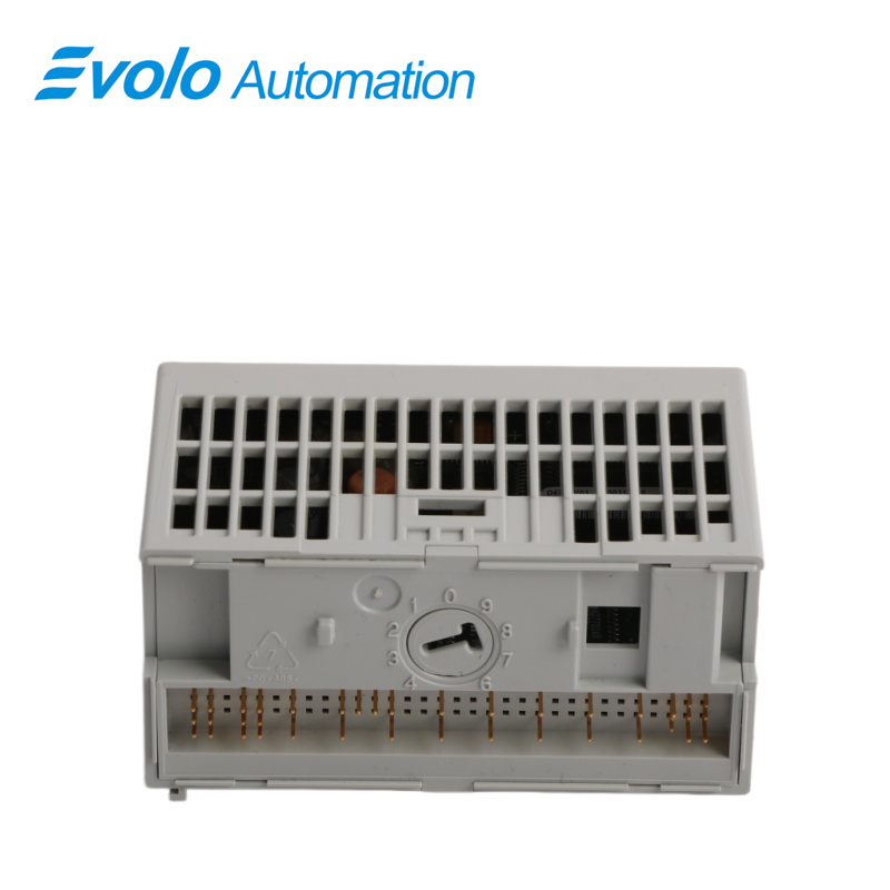
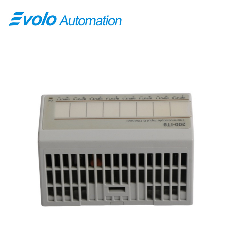
- Overview
- Specifications
- Functional Description
- Applications
- Troubleshooting
- Features
- FAQ
- Recommended Products
Overview
Place of Origin: |
Sweden |
Brand Name: |
ABB |
Model Number: |
S200-IT8 S200IT8 |
Packaging Details: |
Original new Factory Sealed |
Delivery Time: |
5-7 days |
Payment Terms: |
T/T |
Supply Ability: |
In stock |
Specifications
|
Parameter |
Value |
|
Model |
S200-IT8 S200IT8 |
|
Product Type |
Thermocouple Input Unit |
|
Dimensions |
9.3 x 5.3 x 4.5 cm |
|
Weight |
0.085 kg (net), 0.180 kg (gross) |
|
Number of Inputs |
8 |
|
Galvanic Isolation |
Yes |
|
Status Indicator |
Bi-colour LED (green/red) |
|
Resolution |
16-bit |
|
Input Voltage Range |
±76.5 mV DC |
|
Supported Thermocouples |
B, C, E, J, K, N, R, S, T |
|
Thermocouple Range |
B: 300–1800°C; C: 0–2315°C; E: -270–1000°C; J: -210–1200°C; K: -270–1372°C; N: -270–1300°C; R/S: -50–1768°C; T: -270–400°C |
|
Overvoltage Capability |
35 V DC, 25 V AC continuous, 250 V peak |
|
Accuracy (with filter) |
≤0.025% FSR ±0.5°C |
|
Accuracy (without filter) |
≤0.05% FSR ±0.5°C |
|
Input Offset Drift |
±6 µV/°C max |
|
Gain Drift |
10 ppm/°C |
|
Overall Drift |
≤50 ppm/°C of span |
|
Open Thermocouple Detection |
Upscale out-of-range indication |
|
Open Thermocouple Detection Time |
~1 s |
|
Internal Bus Current Consumption |
≤20 mA |
|
Filter |
Programmable |
|
Noise Rejection |
-60 dB @ 60 Hz |
|
Common Mode Rejection |
-115 dB @ 60 Hz, -100 dB @ 50 Hz |
|
System Throughput |
28–325 ms (1 ch), 2.6 s (8 ch) |
|
Operating Temperature |
0 °C to +55 °C |
|
Storage Temperature |
-40 °C to +85 °C |
|
Humidity (Operating) |
5–95% non-condensing |
|
Humidity (Storage) |
5–80% non-condensing |
|
External Power Supply |
24 V DC (19.2–31.2 V DC) |
|
Supply Current |
60 mA @ 24 V DC |
|
Power Dissipation |
3 W max |
|
Unit Identity Code |
1B00 (hex) |
|
Backplane Key Code |
3 |
|
Certifications |
CSA Class I Div 2 (T5), European Ex Zone 2 Group IIC |
Functional Description
S200-IT8 S200IT8 is an analog I/O unit for 8 thermocouple input signals. The 8 input signals are connected to the unit via the screw terminal on the terminal base unit. They are galvanically isolated from the Serial bus (see function block diagram below).
It is possible to deselect unused channels to improve system throughput. Periodic user calibration is supported.
Power for the internal logic is provided via the process power supply.
Applications
Iron and steel smelting plants: Monitoring extreme high-temperature environments in blast furnaces, converters, and heat treatment furnaces.
Glass manufacturing plants: Precise temperature monitoring of melting furnaces and forming molds.
Waste incineration plants: Real-time temperature monitoring of incinerator furnaces and flue gas treatment systems.
Ceramic tunnel kiln plants: Multi-point temperature acquisition for controlling sintering curves.
Coal power plants: Monitoring steam temperatures in superheaters, reheaters, and flue gas systems.
Troubleshooting
Steady red: Indicating a critical fault
Measure:
Replace the unit.
Flashing red: Indicating a noncritical fault (such as open sensor, input out of range, etc.)
Measure:
1. Check cabling and connectors.
2. Check that correct type is selected in the hardware configuration.
3. Replace the unit.
Flashing green: Indicating that the unit is functional but not configured
Measure:
1. Start the program to configure the unit.
2. Check the program.
3. Replace the unit.
Features
Replacement under system power
CE and UL approvement
Software configurable function
Mechanical coding for safe replacement
Safety function on outputs in remote configuration
Variety of termination options
The same I/O units in central andremote configurations
Compatible with I/O 200C
FAQ
Q1: Can the S200-IT8 S200IT8 module directly measure voltage?
Yes, it supports ±100 mV DC voltage input and is commonly used to connect to some small signal transmitters.
Q2: Why is there a large difference between my S200-IT8 S200IT8 module's measured value and the actual temperature on site?
Please check if the polarity of the compensating wires is reversed, or if the thermocouple type selected in the software (e.g., K type mistakenly selected as J type) is incompatible.
Q3: What does it mean when the red light on the S200-IT8 S200IT8 module panel is on?
It may indicate an internal self-test error, an interruption of the external 24V power supply, or a disconnection in all configured channels.
Q4: Does the S200-IT8 S200IT8 module support 3-wire connection?
No. Thermocouples are typically 2-wire; 3-wire or 4-wire connections are specific to RTDs (such as the S200-IR8).
Q5: Do unused channels on the S200-IT8 S200IT8 need to be addressed?
To avoid false alarms, it is recommended to disable unused channels in the software configuration or short-circuit their input terminals.