EN
EN




- Overview
- Specifications
- Description
- Applications
- OPERATION
- Configuration
- FAQ
- Recommended Products
Overview
Place of Origin: |
USA |
Brand Name: |
GE |
Model Number: |
IS230SNAIH4A IS200STAIH2ACB |
Packaging Details: |
Original new Factory Sealed |
Delivery Time: |
5-7 days |
Payment Terms: |
T/T |
Supply Ability: |
In stock |
Specifications
|
Product Name: |
Analog Input Terminal Board |
|
Model Numbers: |
IS230SNAIH4A IS200STAIH2ACB |
|
Manufacturer: |
General Electric |
|
Series: |
Mark VIe |
|
Dimensions: |
16.7 x 14.8 x 5.5 cm |
|
Board Size: |
10.16 cm (W) x 33.02 cm |
|
Weight: |
0.64 kg |
|
Number of Channels: |
16 |
|
Analog Output Current: |
0–20 mA |
|
Maximum Lead Resistance: |
15 Ω |
|
Frequency: |
50/60 Hz |
|
Operating Temperature: |
-30 to +65 °C |
|
Country of Origin: |
United States |
Description
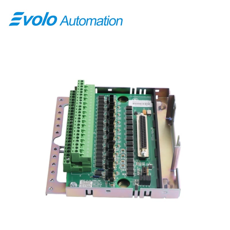
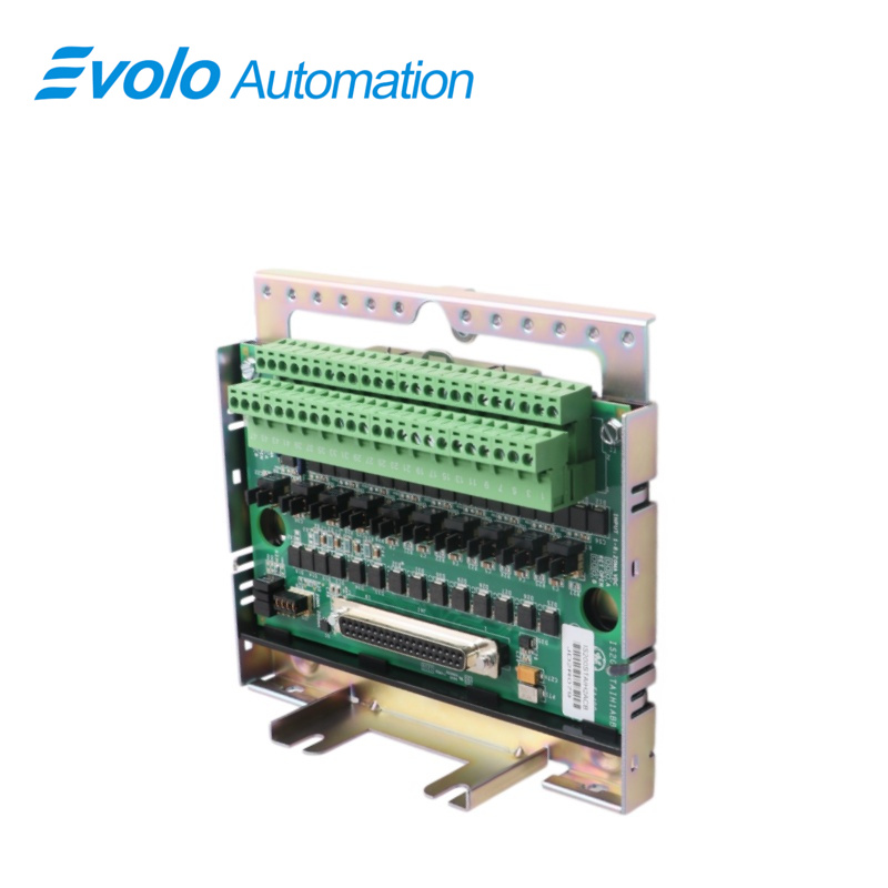
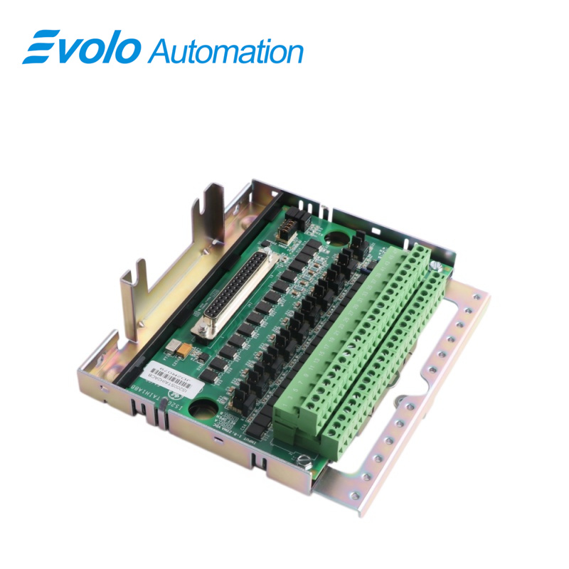
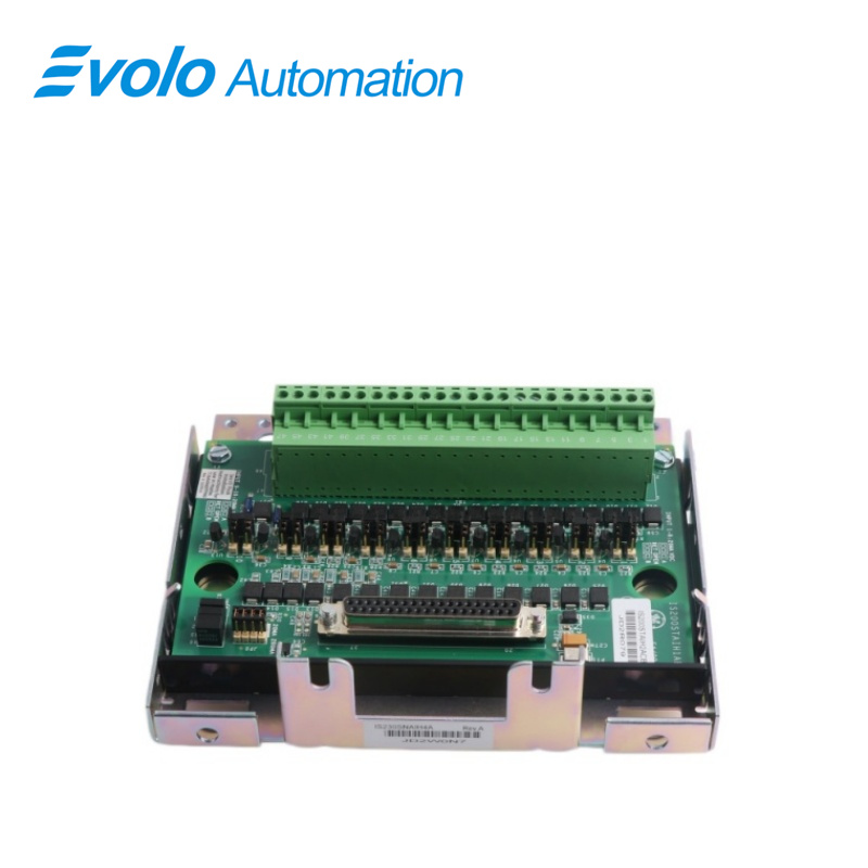
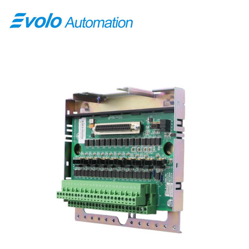
IS230SNAIH4A IS200STAIH2ACB is a Analog Input Terminal Board manufactured and designed by General Electric as part of the Mark Vle Series used in GE Distributed Turbine Control Systems. The Simplex Analog Input (STAl) terminal board is a small analog input terminal board that connects to the pack and accepts 10 analog inputs and two analog outputs. The ten analog inputs support two-wire, three-wire, four-wire, and externally powered transmitters. The two analog outputs are 0-20 mA, but one of them can be jumpered to 0-200 mA current. The board is only available in a simplex configuration. Terminal blocks of high-density Euro-block type are used.
Applications
Thermal power plants: Acquire 4-20mA signals from pressure, flow, and level transmitters.
Nuclear power plants: Used for precision analog signal monitoring of conventional island and auxiliary systems.
Combined cycle power plants: Monitor thermal instrumentation data from gas turbine and boiler systems.
Petrochemical plants: Connect to explosion-proof transmitters to monitor production process parameters.
Natural gas processing plants: Used for pressure monitoring and flow calculation.
Iron and steel metallurgical plants: Monitor pressure in blast furnace and converter cooling water systems and hydraulic stations.
OPERATION
1.Transmitter Power and Input Selection: Ensures convenience by providing 24 V DC power to all transmitters connected to the terminal board, eliminating the need for additional power sources. Moreover, users can select between current and voltage inputs using jumpers to suit different sensor types and applications
2.Analog Output Configurations: Includes two analog output circuits, one fixed at 4–20 mA for standard industrial control, while the other can be configured via jumper for 4–20 mA or 0–200 mA to meet wider application needs
3.Limitations on TMR and TBAl Applications: Due to only one cable connection, the terminal board cannot be used for Triple Modular Redundant (TMR) or Triple-Channel Bumpless Automatic (TBAI) applications
Configuration
A. Current or Voltage Input Selection: Jumpers J1A through J8A determine whether the input signals are configured for current input or voltage input. The appropriate jumper setting should be selected based on the type of input signals being used
B. Input Current Selection: Jumpers J9A and J10A allow users to select the input current level, offering options between 1 mA and 20 mA. This selection should align with the specific requirements of the application
C. Jumper Selection: The configuration of the terminal board involves setting jumpers in specific positions. These jumpers are designated by labels such as J1A through J8A, J1B through J8B, J9A, J10A, J9B, J10B, and J0
D. Output Configuration: Jumper J0 is dedicated to configuring the output of the terminal board. It sets output 1 to either 20 mA or 200 mA, depending on the desired output current level for the application
E. Return Connection for Input Current: Similar to J1B through J8B, jumpers J9B and J10B offer choices for connecting the return path of the input current signals. Users can opt to connect it to the common terminal or leave it open as needed
F. Return Connection Selection: Jumpers J1B through J8B provide options for connecting the return path of the input signals. Users can choose to connect the return to the common terminal or leave it open, depending on the system requirements
FAQ
Q: What are the input span and transmitters of the IS230SNAIH4A IS200STAIH2ACB?
A: The input span of the product is 1–5 V dc across a precision resistor (usually 250 W).
Q: What is the maximum lead resistance of the IS230SNAIH4A IS200STAIH2ACB?
A: The maximum lead resistance is 15 ohms for two-way cable resistance, with a cable length of up to 300 m (984 ft).
Q: What is the load on the output currents of IS230SNAIH4A IS200STAIH2ACB?
A: The load on output currents is 800-ohm burden for 4–20 mA output with PAIC pack and 50-ohm burden for 200 mA output.