EN
EN




- Overview
- Specifications
- Description
- Features
- Installation Guidelines
- Compatibility
- Frequently Asked Questions
- Recommended Products
Overview
Place of Origin: |
USA |
Brand Name: |
GE |
Model Number: |
IS200VAICH1DAA IS200VAICH1D |
Packaging Details: |
Original new Factory Sealed |
Delivery Time: |
5-7 days |
Payment Terms: |
T/T |
Supply Ability: |
In stock |
Specifications
|
Part Number: |
IS200VAICH1DAA / IS200VAICH1D |
|
Manufacturer: |
General Electric |
|
Country of Manufacture: |
United States of America (USA) |
|
Product Type: |
Analog Input Board |
|
Series: |
Mark VI |
|
Number of Channels: |
24 |
|
Input Span: |
4-20 mA |
|
Power Consumption: |
Less than 31 mW |
|
Technology: |
Surface mount with conformal coating |
|
Conversion Accuracy: |
16-bit A/D converter with 14-bit resolution |
Description
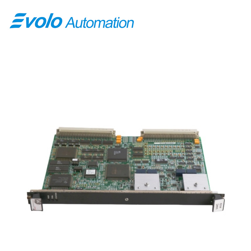
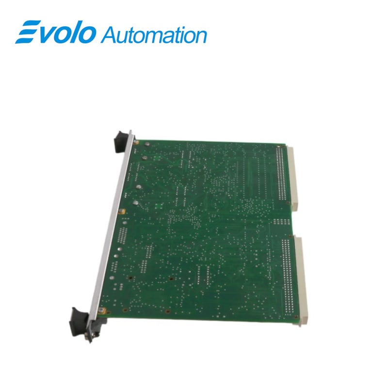
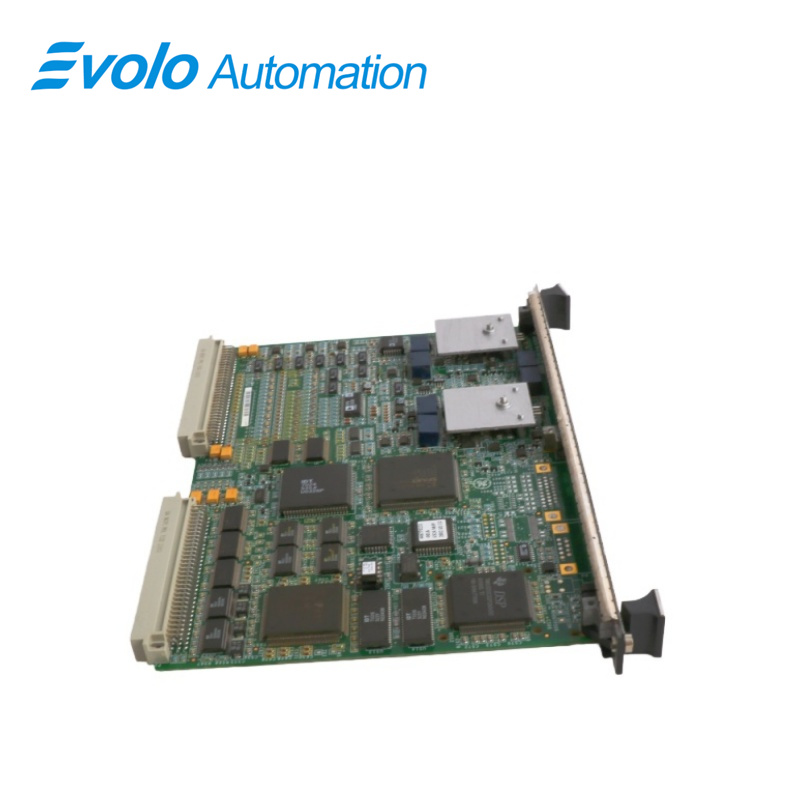
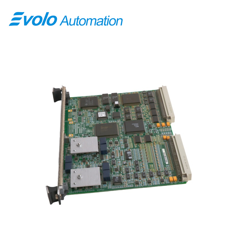
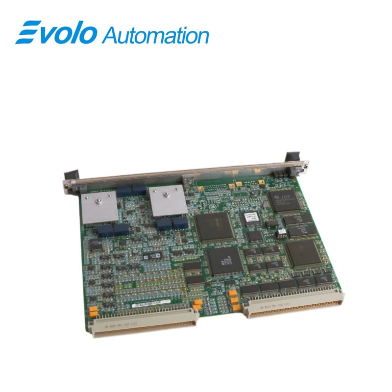
IS200VAICH1DAA IS200VAICH1D is an Analog Input Board developed by GE. It is a part of the Mark VI control system. The versatility of the VAIC extends to its support for both simplex and triple modular redundant (TMR) applications, providing adaptability to different system configurations. While the simplex configuration may lack the inherent redundancy of the TMR setup, it is a suitable and efficient solution for applications where a single VAIC can adequately meet the system's requirements. The simplicity of the setup facilitates ease of integration and maintenance in scenarios where the additional fault tolerance provided by TMR is not a critical requirement.
Features
1 Triple Modular Redundant (TMR) Configuration: In a TMR application, the VAIC plays a crucial role in enhancing system reliability and fault tolerance. The input signals from the terminal board are fanned out to three separate VME board racks labeled R, S, and T, each hosting its own instance of the VAIC. This triplex configuration ensures redundancy, with each VAIC independently processing the input signals.
2 The output signals are meticulously driven using a proprietary circuit that harmonizes the contributions of all three VAICs. This collaborative effort ensures that the desired output current is achieved. In the unfortunate event of a hardware failure in one of the VAICs, a failover mechanism is triggered. The faulty VAIC is promptly removed from the output circuit, while the remaining two VAICs seamlessly continue operations, maintaining the correct output current. This redundancy significantly enhances the reliability and fault tolerance of the system, ensuring continuous operation even in the face of hardware failures.
3 Simplex Configuration: In a simplex configuration, the VAIC operates in a more straightforward manner. The terminal board provides input signals to a single instance of the VAIC. In this scenario, there is a one-to-one relationship between the terminal board and the VAIC. The single VAIC, acting as the sole processing unit, is responsible for handling all input signals and generating the necessary output currents.
Installation Guidelines
1 When establishing cable connections to the TBAl (Terminal Board Analog Input) terminal boards, the process involves interfacing with the J3 and J4 connectors located on the lower portion of the VME (Versa Module Eurocard) rack. These connectors are specifically designed as latching type connectors, emphasizing a secure and stable connection for the cables that link the terminal boards to the broader system.
2 Identifying Connection Points: The J3 and J4 connectors on the lower part of the VME rack are designated connection points for interfacing with the TBAl terminal boards. The latching type connectors are chosen to ensure that the cables remain securely connected, minimizing the risk of inadvertent disconnection or signal interruptions.
3 Cable Attachment: To establish the cable connections, carefully attach the cables to the J3 and J4 connectors on the VME rack. The latching mechanism is designed to provide a reliable and robust connection. Ensure that the cables are securely latched into place to guarantee stable communication between the TBAl terminal boards and the VME rack.
4 Powering Up the VME Rack: With the cable connections successfully established, proceed to power up the VME rack. This involves restoring electrical power to the rack, allowing the system to become operational. The power-up sequence is a critical step, and it ensures that the TBAl terminal boards and the entire system are ready for normal operation.
5 Checking Diagnostic Lights: After powering up the VME rack, direct attention to the diagnostic lights located at the top of the front panel. These lights serve as indicators of the system's health and status. Different combinations of illuminated lights or specific patterns may convey information about the system's functionality, potential errors, or diagnostic information.
6 Normal Operation: A set of predefined diagnostic light patterns indicates that the system is functioning correctly, and the TBAl terminal boards are properly integrated.
7 Fault or Error Indication: Deviations from the normal light patterns may indicate faults or errors in the system. Consult the system documentation to interpret the specific diagnostic light patterns and take appropriate corrective measures if necessary.
Compatibility
1 The design of the TBAl demonstrates a forward-thinking approach, particularly in its ability to accommodate higher load resistance for 20 mA outputs. One notable feature is the provision of a drive voltage that can reach up to 18 V at the terminal board screw terminals. This capability is strategically integrated to address challenges associated with higher load resistances, ensuring the board's adaptability to a diverse range of operational scenarios.
2 When dealing with 20 mA outputs, the availability of a drive voltage of up to 18 V becomes instrumental. This feature enables the TBAl to effectively overcome the impedance presented by loads of up to 800 ohm. Moreover, the design takes into account the potential impact of extended wiring distances, allowing for the operation of the terminal board into loads of 800 ohm even with the inclusion of a 1000 ft length of #18 wire.
3 The provision of a drive voltage up to 18 V plays a crucial role in maintaining signal integrity over extended distances and when confronted with higher load resistances. This is particularly relevant in industrial and control system applications where precise and reliable analog signal transmission is imperative for accurate monitoring and control processes.
4 The TBAl's capability to operate into loads of 800 ohm with the inclusion of 1000 ft of #18 wire showcases a margin of robustness. This margin not only accommodates the inherent resistance introduced by the wiring but also ensures that the terminal board can reliably deliver the required current in challenging environments.
Frequently Asked Questions
Q: What is IS200VAICH1DAA IS200VAICH1D?
A: IS200VAICH1DAA IS200VAICH1D is an Analog Input/Output Board developed by General Electric under the Mark VI series, designed for monitoring and processing analog signals in industrial automation systems.
Q: How does the analog input system handle hardware limit checking of IS200VAICH1DAA IS200VAICH1D?
A: Analog inputs include hardware limit checking with preset high and low levels near the extremes of the operating range. If an input exceeds these limits, a logic signal is triggered, stopping further scanning for that input. Any hardware limit breach generates a composite diagnostic alarm, L3DIAG VAIC, indicating a board-wide issue. Individual input diagnostics can be reviewed in the toolbox.
Q: What is the significance of the composite diagnostic alarm of IS200VAICH1DAA IS200VAICH1D?
A: L3DIAG VAIC serves as a comprehensive diagnostic alarm for the entire board, summarizing potential issues caused by any analog input exceeding hardware limits. It allows operators to quickly identify board-level problems, while detailed diagnostics for each input are accessible through the toolbox for in-depth analysis.
Q: How are diagnostic signals managed in the analog input system of IS200VAICH1DAA IS200VAICH1D?
A: Diagnostic signals are managed individually and can be latched. Once triggered, a signal remains active until manually reset using the RESET DIA command. This latching mechanism ensures that diagnostic events are captured and retained for troubleshooting.
Q: How does the analog input system handle system limit checking of IS200VAICH1DAA IS200VAICH1D?
A: Each analog input supports system limit checking with configurable high and low thresholds. Users can enable or disable these limits and select latching or non-latching alarm modes. When limits are exceeded, the RESET SYS signal can be used to reset the system, allowing normal operation to resume.