Get a Free Quote

Our representative will contact you soon.
Email
Name
Company Name
Message
0/1000
is200tvbah1acc analog terminal board -0

For GE

Home >  Products >  For GE

IS200TVBAH1ACC Analog Terminal Board

  • Overview
  • Quick Detail
  • Description
  • Applications
  • Features
  • Installation, Operation, and Jumper Configuration
  • Operation
  • FREQUENTLY ASKED QUESTIONS
  • Recommended Products
Overview

Place of Origin:

USA

Brand Name:

GE

Model Number:

IS200TVBAH1ACC

Packaging Details:

Original new Factory Sealed

Delivery Time:

5-7 days

Payment Terms:

T/T

Supply Ability:

In stock

Quick Detail

Manufacturer:

GE

Model:

IS200TVBAH1ACC

System Compatibility:

Mark Vle control system

Function:

Vibration Terminal Board, signal interface for I/O packs

Supported Sensors:

Eddy-current (position/velocity), seismic (velocity), Velomitors, accelerometers (velocity)

Input Protection:

Transient suppression for 24-point screw terminals

Power Supply:

+28 V from customer; -28 V via WNPS daughter board for Bently Nevada sensors

I/O Connectors:

37-pin connectors to I/O packs

Buffered Outputs:

9-pin and 25-pin DIN connectors, BNC for third-party monitoring

Configuration Jumpers:

JPxA, JPxB, JPxC

Application:

Simplex or TMR configurations

Description

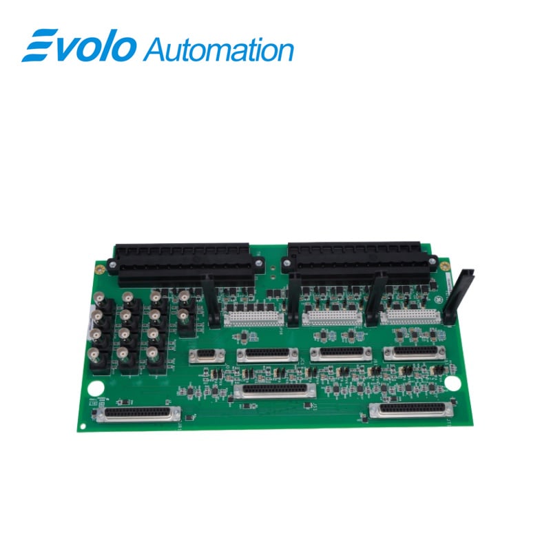
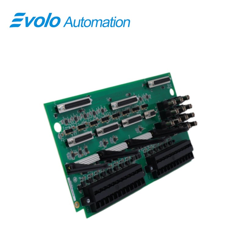
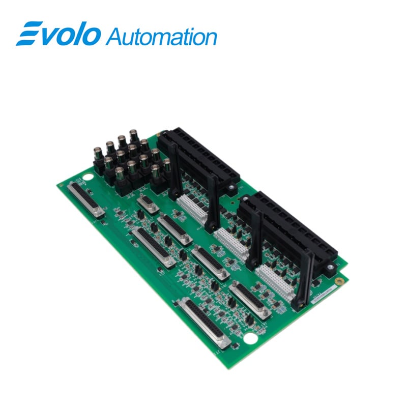
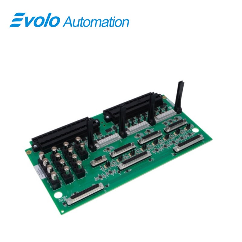
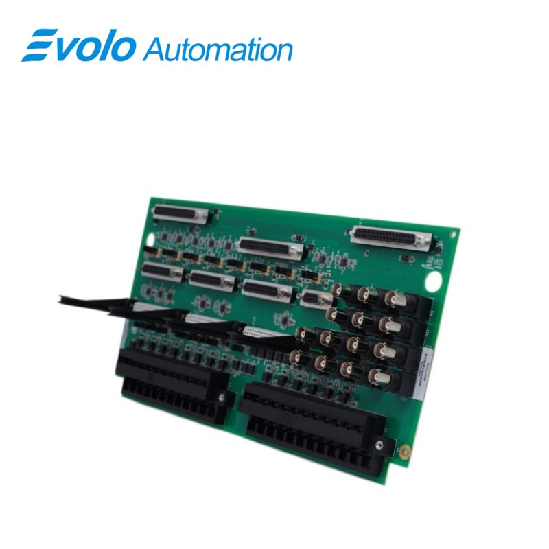
IS200TVBAH1ACC is a Vibration Terminal Board developed by GE.It is a part of Mark Vle control system.The board serves as a signal interface board for the l/O packs Mark Vle PVIB or Mark VleS VIB.Eddy-current (position and velocity), seismic (velocity), Velomitors, and accelerometers with integrated outputs (velocity) sensors have a direct vibration interface.It also gives charge amplifiers a dynamic pressure interface.Transient suppression protects the terminal board input signals entering through the two 24-point screw terminals from high voltages caused by electrical disturbances.Jumpers JPxA and JPxC, located to the left of the 37-pin I/O pack connectors and to the right of the 24-point screw terminals, power the various sensors and detect open circuits.

Applications

Thermal and nuclear power plants: Monitor bearing vibration, shaft displacement, and speed of steam turbines and generators to prevent catastrophic unit damage due to imbalance or misalignment.

Oil and gas (refineries/compressor stations): Used for monitoring large centrifugal compressors and gas turbine-driven pump units, providing real-time monitoring of unit operating status and supporting Safety Instrumented Systems (SIS) for critical processes.

Chemical and process control plants: Utilize this board for preventative maintenance in monitoring reactor agitators or large fan systems requiring continuous operation.

Mining and mineral engineering: Used for monitoring drive motors in large mills or conveying systems, adaptable to extremely harsh dust and vibration environments.

Features

The input signals are routed to the I/O packs via 37-pin connectors on the right side. The TVBA is suitable for both simplex and TMR applications. TMR applications distribute the signal across three I/O packs. The input signals' buffered outputs are routed to 9 and 25 pin DIN connectors to feed the Bently Nevada 3xx monitoring system.

A bayonet nut connection (BNC) is also included for each buffered output to feed third-party monitoring equipment. Use the JPxB jumpers to the left of the 37-pin I/O pack connectors to configure the output buffers for the appropriate sensor. Channels 1 through 13 and 14 of the I/O pack are routed to buffered outputs for external use.The l/O pack receives power from a +28 V supply supplied by the customer

The WNPS daughter board supplies the -28 V power required to power the Bently Nevada sensors for the TVBAH#A terminal boards only, one for simplex and three for TMR configurations.The removable daughterboar (s) convert the +28 V power from the source to -28 V power.

Installation, Operation, and Jumper Configuration
The board accepts 14 sensor inputs, which are directly connected to two 24-point I/O terminal blocks. Each block is held together by two screws that accept wires up to 12 AWG.
Each terminal block has its own shield termination attachment point. Only 13 of the 14 channels can be processed by the I/O pack. The 14th channel is routed to the buffered output stage, where it is used by Bently Nevada equipment (with TVBAH2A, H2B, S2A, or S2B)
Installation
The installation process for the TVBA (Transducer Voltage Bias Assembly) involves various components and connections to ensure the system functions correctly. Here's an in-depth explanation of the installation procedure:
Sensor Inputs:
The TVBA accepts a total of 14 sensor inputs.
These sensor inputs are wired directly to two I/O terminal blocks, with each block securely fastened using two screws.
Each terminal block is equipped with 24 terminals designed to accept wires as large as #12 AWG, ensuring the capacity to handle a variety of wire sizes.
Adjacent to each terminal block, a shield termination attachment point is provided.This point plays a crucial role in grounding and electromagnetic shielding, maintaining signal integrity
Input Channels 1-8:
These channels support various sensors, including Proximitors, Seismics, Accelerometers (only in channels 1, 2, and 3), and Velomitors.
A current-limited -24V power supply is allocated per channel, ensuring that sensor components receive stable power.
JPxA jumpers are available for configuring open circuit checks and providing a constant 3mA current feed for Velomitors.
JPxB configurations are available to set the JA1 and JB1 outputs for compatibility with the Bently Nevada 3500 rack.
JPxC configurations enable PR0xL to be set as Open for true differential input or connected to PCOM for a -24V return
Input Channels 9-12:
These channels exclusively support Proximitors sensors.
Each channel is equipped with a current-limited -24V power supply.
No jumper configuration is required for these channels
Input Channel 13:
Channel 13 supports Proximitors or Keyphasor proximity sensors.
Similar to other channels, it features a current-limited -24V power supply,
No jumper configurations are necessary for this channel.
-28V Power Supply Board (WNPS):
The WNPS board plays a vital role in the installation, converting the +28V power supply from the PVIB (Proximitor/Velomitor Interface Board) to the -28V power
required by the current-limited -24V outputs.
There is one WNPS board allocated per PVIB.
Each WNPS board is equipped with independent +28V inputs and a common -28V bus shared among all three WNPS boards.
Operation

The TVBA(Transducer Voltage Bias Assembly) is designed to accommodate and support a total of 14 sensor connections.These connections are categorized into different types and serve various monitoring and feedback purposes within the system. Here's a concise description of the supported sensor connections:

Vibration or Position Sensors (Circuits 1 through 8): The TVBA provides support for eight sensor circuits designed for Vibration or Position sensing. These circuits are versatile and can monitor a range of parameters related to vibration and position within the system

Position Sensors (Circuits 9 through 12): Four sensor circuits, numbered 9 through 12, are dedicated solely to Position sensing. These circuits are optimized for precise position monitoring applications.

Reference Probe (Keyphasor) or Position Sensor (Circuit 13): Circuit 13 offers flexibility by accommodating either a Reference Probe (Keyphasor) or a Position Sensor. This adaptability allows for monitoring critical system parameters or serving as a reference point for specific applications.

Reference Probe (Keyphasor) or Position Sensor (Circuit 14): Circuit 14 is specialized for use with the Bently Nevada 3500 interface, supporting either a Reference Probe (Keyphasor) or a Position Sensor. This interface is tailored to meet the specific requirements of the Bently Nevada 3500 system.

FREQUENTLY ASKED QUESTIONS

Q: What is IS200TVBAH1ACC?
A: IS200TVBAH1ACC is a Vibration Terminal Board developed by GE, designed for interfacing vibration monitoring signals within industrial control systems.

Q: How are input signals routed to the I/O packs of IS200TVBAH1ACC?
A: The input signals are routed to the I/O packs through 37-pin connectors located on the right side of the board.

Q: What is the purpose of the WNPS daughter board of IS200TVBAH1ACC?
A: The WNPS daughter board provides -28 V power required for Bently Nevada sensors used with the TVBAH#A terminal boards. It supports one unit in simplex configurations and up to three units in TMR (Triple Modular Redundancy) configurations.

Q: How are the output buffers configured for the appropriate sensor of IS200TVBAH1ACC?
A: The output buffers are configured using JPxB jumpers located to the left of the 37-pin I/O pack connectors. These jumpers allow proper matching with the connected sensor type.

Q: Where are the buffered outputs routed for external use of IS200TVBAH1ACC?
A: Channels 1 through 13 and channel 14 of the I/O pack are routed to buffered outputs, making them available for external monitoring and system integration.

Get a Free Quote

Our representative will contact you soon.
Email
Name
Company Name
Message
0/1000
email goToTop

Evolo Automation is not an authorized distributor unless otherwise specified, representative, or affiliate of the manufacturer of this product. All trademarks and documents are the property of their respective owners and are provided for identification and informational.