EN
EN




- Overview
- Quick Detail
- Description
- Applications
- Features
- Product Attributes
- FREQUENTLY ASKED QUESTIONS
- Recommended Products
Overview
Place of Origin: |
USA |
Brand Name: |
GE |
Model Number: |
IS200EXHSG3AEC |
Packaging Details: |
Original new Factory Sealed |
Delivery Time: |
5-7 days |
Payment Terms: |
T/T |
Supply Ability: |
In stock |
Quick Detail
|
Part Number: |
IS200EXHSG3AEC |
|
Manufacturer: |
General Electric |
|
Country of Manufacture: |
United States (USA) |
|
Number of Relay Channels: |
12 |
|
Size (HxWxD): |
8.26 cm x 4.19 cm x 12.1 cm |
|
Technology: |
Surface-mount |
|
Series: |
EX2100 |
|
Function: |
Exciter HS Relay Driver Board |
|
System: |
GE Speedtronic EX2100 Gas Turbine Control System |
|
Excitation Control Functions: |
Drives DC contactors (K41) and pilot relays for de-excitation and field flashing |
|
Pilot Relays for Field Flashing: |
53A, 53B |
|
Pilot Relays for De-excitation: |
KDEP |
|
Signal Conditioning: |
De-excitation signals from EDEX, crowbar signals from EXDE, output to EMIO |
|
Power to Relay Coil: |
125 V DC nominal, range 100–140 V DC |
|
Power to Relay Contacts: |
24 V DC from exciter cabinet |
|
Resistive Load: |
2 A at 28 V DC |
|
Inductive Load: |
1 A at 28 V DC for 0.007 s (L/R) |
|
Suppression: |
External, none on board |
|
Connectors: |
J505 (M1), J508 (M2), J515 (C, no de-excitation/crowbar signals) |
|
Plugs: |
J12M1 (70 V DC M1), J12M2 (70 V DC M2) |
|
Primary Relay Drivers: |
K41 (M1, M2, C), K53A, K53B, KDEP |
|
Functions: |
Close function contactors, flashing pilot relays, controlled de-excitation |
|
Application: |
Excitation system control and monitoring for gas turbines |
Description
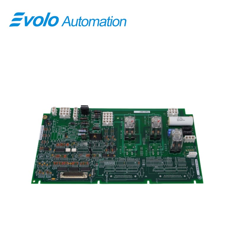
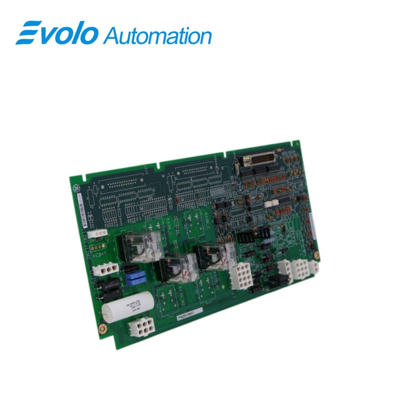
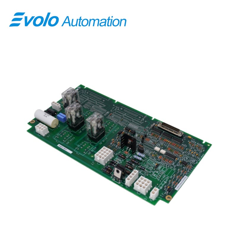
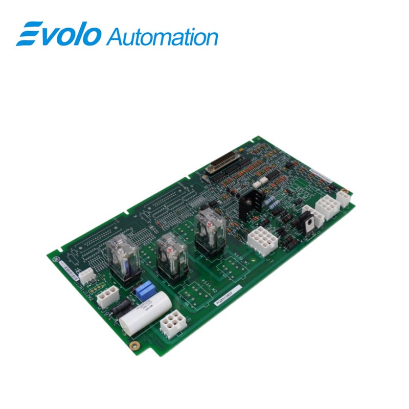
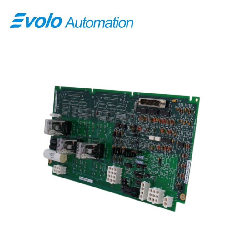
IS200EXHSG3AEC is a Exciter HS Relay Driver Board developed by GE. It is part of the GE Speedtronic EX2100 gas turbine control system. The Exciter High-Speed Relay Driver (EXHS) board is an integral component of the EX2100 Excitation Control system, playing a crucial role in providing drivers for various components essential for excitation control in industrial applications.
Applications
Power Generation Facilities
Gas/Steam Turbine Power Plants: Installed in GE-manufactured turbine control cabinets as part of an Automatic Voltage Regulator (AVR), ensuring stable generator output voltage and safe synchronization with the grid.
Hydropower Power Plants: Used for excitation control of hydroelectric generators, supporting static excitation mode.
Nuclear Power Plants: The EX2100e system (containing such boards) is commonly used for excitation management of nuclear power generator sets.
Heavy Industrial Production Plants
Steel and Metallurgical Plants: Used for excitation systems driving large generator sets requiring extremely high current protection and precise control in high-load processes such as steel rolling.
Cement and Paper Mills: Used in crushers, mills, or slurry pump systems driven by large synchronous motors.
Oil and Gas: Manages turbine drive operation in petrochemical complexes' self-contained power plants or large compressor drive systems (such as LNG compressors).
Maritime and Shipping: Large Ship Propulsion System: Used in ship propulsion systems employing turbine technology, responsible for the excitation control of generator sets to ensure a stable power supply during navigation.
Features
Excitation Control Functions: The board is primarily responsible for driving the DC contactors (41) and pilot relays required for de-excitation and field flashing within the EX2100 Excitation Control system.These components are vital for controlling the flow of electrical current and ensuring proper operation of the excitation system.
Pilot Relays for Field Flashing: On the board, pilot relays are provided for the flashing relays 53A and 53B, which are essential for field flashing operations. These relays play a crucial role in initiating and controlling the process of establishing the field current in synchronous generators.
Pilot Relays for De-excitation: Additionally, the board includes pilot relays for the de-excitation relay KDEP, These relays are instrumental in the safe and controlled de-energization of the excitation system, preventing excessive voltage buildup and ensuring operational safety.
Signal Conditioning and Transmission: Performs signal conditioning for de-excitation status signals originating from the Exciter De-Excitation Board (EDEX) and crowbar status signals from the De-Excitation Control Boar (EXDE). These conditioned signals are then transmitted to the Excitation Monitoring and Instrumentation Output (EMIO) system for further processing and monitoring.
Product Attributes
Power to Relay Coil: The relay coil receives power from J9, providing a nominal voltage of 125 V DC. It is important to note that the voltage supplied to the coil should range between 100 V DC (minimum) and 140 V DC (maximum) to ensure optimal performance
Power to Relay Contacts: Power for the relay contacts is sourced from the exciter cabinet, delivering a nominal voltage of 24 V DC. This voltage is utilized for controlling the operation of the relay contacts within the system.
Relay Break Characteristics: The characteristics of the relay break are essential for determining its performance under different load conditions:
Resistive Load: The relay can handle a resistive load of up to 2 A at 28 V DC, ensuring reliable operation when switching resistive loads.
Inductive Load: For inductive loads, the relay can manage a current of 1 A at 28 V DC for a duration of 0.007 seconds (L/R). This specification indicates the relay's capability to handle sudden changes in current flow, typical in inductive load scenarios
Suppression: Suppression for the relay coil is supplied externally, with no suppression provided on the EXHS board itself. This ensures that any voltage spikes or transients generated during the operation of the relay coil are effectively mitigated, preventing potential damage to the system components
FREQUENTLY ASKED QUESTIONS
Q: What is IS200EXHSG3AEC?
A: IS200EXHSG3AEC is an Exciter HS Relay Driver Board used in the GE Speedtronic EX2100 gas turbine control system. It is responsible for driving relay-based control functions within the excitation system.
Q: What are the primary functions of the relay drivers on the IS200EXHSG3AEC?
A: The relay drivers on the EXHS board include K41 (for M1, M2, and C), which control the close function contactors. K53A and K53B are used to manage the flashing pilot relays, while KDEP functions as the single de-excitation pilot relay.
Q: What are the purposes of the three 25-pin connectors, J505, J508, and J515 of IS200EXHSG3AEC?
A: These connectors are used to interface with the EMIO (Excitation Monitoring and Instrumentation Output) boards. J505 connects to M1, J508 connects to M2, and J515 connects to C. Notably, J515 does not carry de-excitation and crowbar signals.
Q: What signals do the connectors J505, J508, and J515 carry of IS200EXHSG3AEC?
A: The connectors carry similar types of signals and share comparable wiring configurations. They transmit control signals and operational data between the EXHS board and the EMIO boards, supporting coordinated monitoring and control of the excitation system.
Q: What is the purpose of plugs J12M1 and J12M2 of IS200EXHSG3AEC?
A: Plugs J12M1 and J12M2 provide 70 VDC input from the M1 and M2 power supplies, respectively. This voltage is used for auxiliary contact wetting, ensuring reliable contact performance and reducing wear over time.
Q: How does the board contribute to the overall operation of the excitation control system?
A: The board supplies relay driving capability for key excitation components such as contactors and pilot relays. By ensuring precise and reliable control of these elements, it enhances the stability, safety, and overall performance of the excitation control system in industrial environments.