EN
EN




- Overview
- Specifications
- Description
- Applications
- Functionality and I/O
- Installation
- Frequently Asked Questions
- Recommended Products
Overview
Place of Origin: |
USA |
Brand Name: |
GE |
Model Number: |
IS200EHPAG1AFD |
Packaging Details: |
Original new Factory Sealed |
Delivery Time: |
5-7 days |
Payment Terms: |
T/T |
Supply Ability: |
In stock |
Specifications
|
Part Number: |
IS200EHPAG1AFD |
|
Manufacturer: |
General Electric |
|
Series: |
EX2100 |
|
Product Type: |
Gate Pulse Amplifier Board |
|
Country of Manufacture: |
United States of America (USA) |
|
Operating Temperature: |
-30°C to +65°C |
|
Control Power: |
125 VDC or 24 VDC |
|
PCB Coating: |
Conformal Coating |
|
Input Signals: |
Receives control pulses from DSPX or EMIO boards |
Description
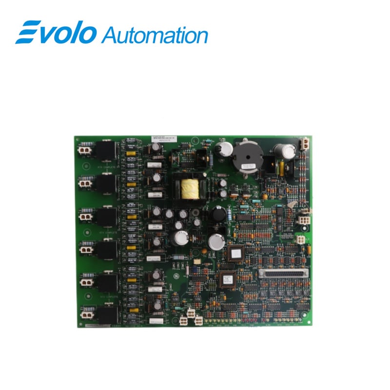
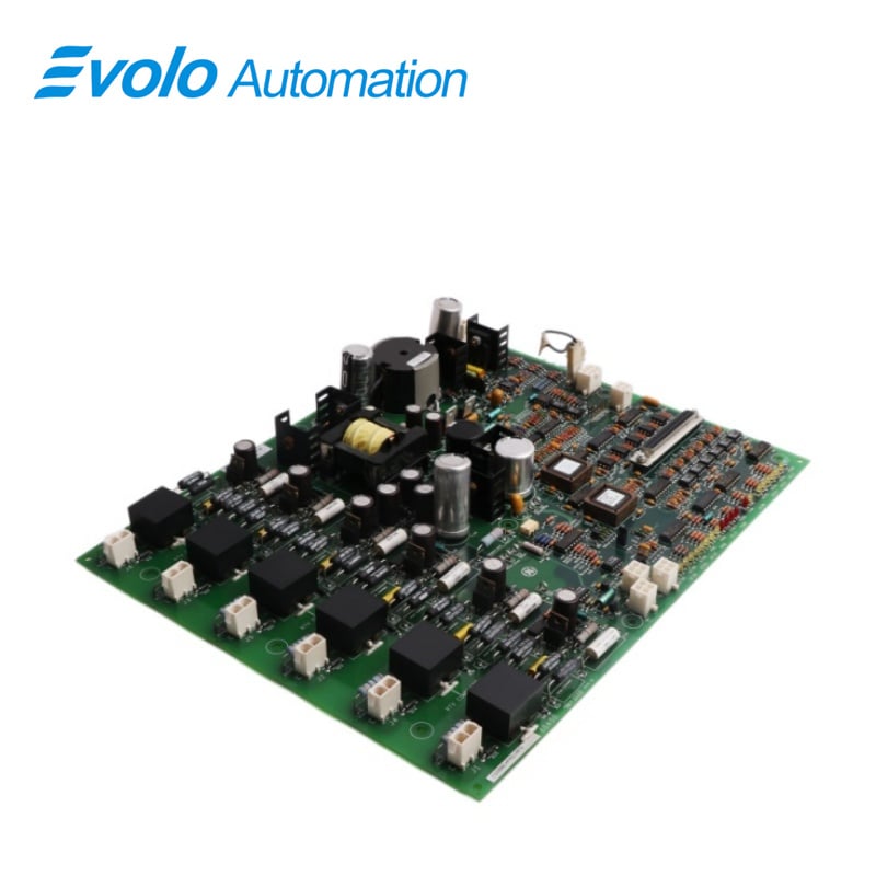
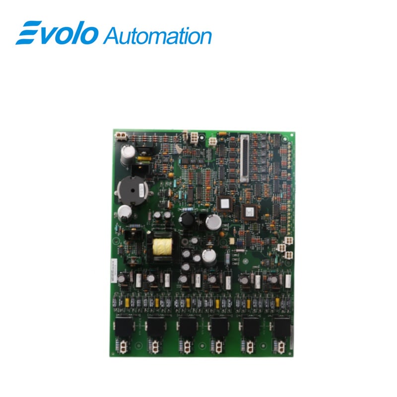
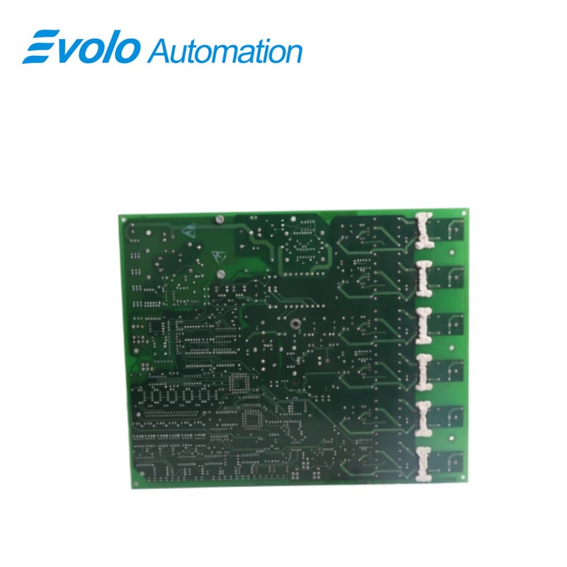
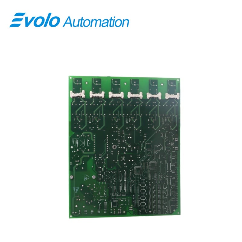
IS200EHPAG1AFD is an Gate Pulse Amplifier Board developed by GE. It is a part of the EX2100 controI system.The Gate Pulse Amplifier Board (EHPA) is responsible for receiving gate commands from the ESEL and controlling the gate firing of up to six SCRs on the Power Bridge. Additionally, it serves as the interface for current conduction feedback, as well as monitoring bridge airflow and temperature.
Applications
Large thermal power plants: GE EX2100/EX2100e static excitation systems for 600MW and above supercritical units.
Nuclear power plants: High-reliability excitation power regulation for main generator units.
Large synchronous motors: Excitation drive control for ultra-high power motors in steel plants, mining crushers, etc.
Functionality and I/O
1 Power Supply: Powered by a nominal 125 V DC power source supplied from the EPDM. An onboard DC/DC converter ensures consistent power supply for SCR gating operations across the full range of input supply voltage.
2 LED Indicators: LEDs provide visual indication of various system parameters, including EHPA power supply, input gate commands from ESEL, outputs to the SCRs, currents into the bridge, line filter, cooling fan rotation, bridge temperature, and alarms or fault conditions.
3 Gate Control and SCR Firing: Receives gate commands from the ESEL and controls the gate firing of up to six SCRs on the Power Bridge, ensuring precise control over the excitation process.
4 Bridge Monitoring: Facilitates current conduction feedback to monitor currents into the bridge, maintaining optimal operation and preventing overloading or imbalance.
5 Airflow and Temperature Monitoring: Serves as an interface for monitoring bridge airflow and temperature, enabling detection and response to variations in environmental conditions for proper cooling and temperature regulation.
Installation
1 Ensure System De-energization: Before initiating the replacement process, ensure that the excitation system, where the EHPA board is housed, has been completely de-energized to prevent any electrical hazards.
2 Safety Precautions: Open the door of the Power Conversion Cabinet and conduct thorough testing of all electrical circuits to confirm that power has been successfully turned off. Take necessary precautions to avoid accidental contact with live circuits.
3 Verify LEDs: Check that all LEDs are switched off, indicating that power has been effectively shut down.
4 Labeling of Cables: Inspect and ensure that all cables connected to the EHPA board are clearly labeled with the correct connector names, as indicated on the board itself. Proper labeling simplifies the reconnection process.
5 Disconnect Cables: With caution, disconnect all cables from their respective connectors on the EHPA board. Handle the cables carefully to avoid damage and ensure smooth reinstallation.
6 Removal of the Board: Carefully remove the existing EHPA board from its mounting location within the equipment. Exercise caution to prevent any damage to the board or surrounding components.
7 Verification of Replacement Board: Before proceeding with installation, carefully inspect the replacement EHPA board to confirm that all jumpers are correctly positioned, matching the configuration of the original board.
8 Installation of Replacement Board: Insert the replacement board into its designated mounting location within the equipment. Ensure proper alignment and secure placement to prevent any loose connections or misalignment issues.
9 Reconnection of Cables: Reconnect all cables that were previously disconnected in step 5, ensuring that each cable is securely fastened and properly tightened to its respective connector on the replacement board.
10 Final Checks: Once all cables are reconnected, perform a final inspection to verify the integrity of the installation. Double-check the tightness of connections and ensure that no hardware or debris has been left inside the equipment.
Frequently Asked Questions
Q: What is IS200EHPAG1AFD?
A: It is an Exciter Gate Pulse Amplifier Board developed by GE under the EX2100 series.
Q: What signals trigger an alarm in the excitation system of IS200EHPAG1AFD?
A: Alarms are triggered by signals from the line filter, fans, temperature switches (170°C and 190°C), and when the RTD exceeds a defined alarm threshold.
Q: What conditions lead to a temperature trip in the system of IS200EHPAG1AFD?
A: A temperature trip occurs if both thermal switches are triggered or if the RTD exceeds a specified fault threshold, indicating critical temperature levels.
Q: What are the failure modes that result in bridge shutdown of IS200EHPAG1AFD?
A: Bridge shutdowns occur due to either a temperature trip or a Gate Pulse Amplifier (GPA) failure. In both single and parallel bridge configurations, the GPA stops gating unless manual coolant trips are disabled.