EN
EN




- Overview
- Specifications
- Description
- Applications
- FEATURES
- SPECIAL HANDLING
- REPAIR/REPLACEMENT
- FAQ
- Recommended Products
Overview
Place of Origin: |
Sweden |
Brand Name: |
ABB |
Model Number: |
IMDSM04 |
Packaging Details: |
Original new Factory Sealed |
Delivery Time: |
5-7 days |
Payment Terms: |
T/T |
Supply Ability: |
In stock |
Specifications
|
Parameter |
Value |
|
Model |
IMDSM04 |
|
Description |
Pulse Input Auxiliary Module |
|
Power Supply Voltages |
±5 VDC Logic Supply (±5%); ±24 VDC I/O Supply (+12%, -10%) |
|
Current Consumption |
5 VDC: 1.4 A typical, 1.5 A max; 24 VDC: 62 mA typical, 70 mA max |
|
Input Voltages |
Range 1 (5 VDC): 4.0–6.0 VDC; Range 2 (24 VDC): 21.6–27.0 VDC; Range 3 (Preamplifiers): 50 mV–10 V peak-to-peak |
|
Maximum Input Signal Current |
Range 1: 14.8 mA at 6 VDC; Range 2: 8.4 mA at 24 VDC; Range 3: 0.4 mA at 10 V peak-to-peak |
|
Logic 1 Input Voltages |
Range 1: 4–6 VDC; Range 2: 21.6–27 VDC; Range 3: 25 mV–5 V peak |
|
Logic 0 Input Voltages |
Range 1: 0–1 V; Range 2: 0–2 V; Range 3: -5 mV to -25 mV peak |
|
Debounce Times |
ON: 8.5 ms typical; OFF: 8.5 ms typical |
|
Input Signal Frequency Limit |
Upper frequency for using debounce: 40 Hz |
|
Mode Accuracy |
Totalize: ±0 counts; Frequency Count: ±1 count; Period Determination: ±1 count |
|
Maximum Input Frequency |
50 kHz (50% duty cycle) |
|
Timebase Accuracy |
±0.033% |
|
Isolation Voltage |
150 V RMS channel-to-channel; 350 V RMS inputs-to-logic |
|
Surge Withstand |
Meets IEEE Surge Capability Standard 472-1974 on all debounced inputs |
|
EMI/RFI Recommendation |
Keep cabinet doors closed; maintain ≥2 m distance from communication equipment |
|
Operating Temperature |
0° to 70°C (32° to 158°F) |
|
Relative Humidity |
5% to 95% up to 55°C; 5% to 45% at 70°C (non-condensing) |
|
Atmospheric Pressure |
Sea level to 3 km (1.86 miles) |
Description
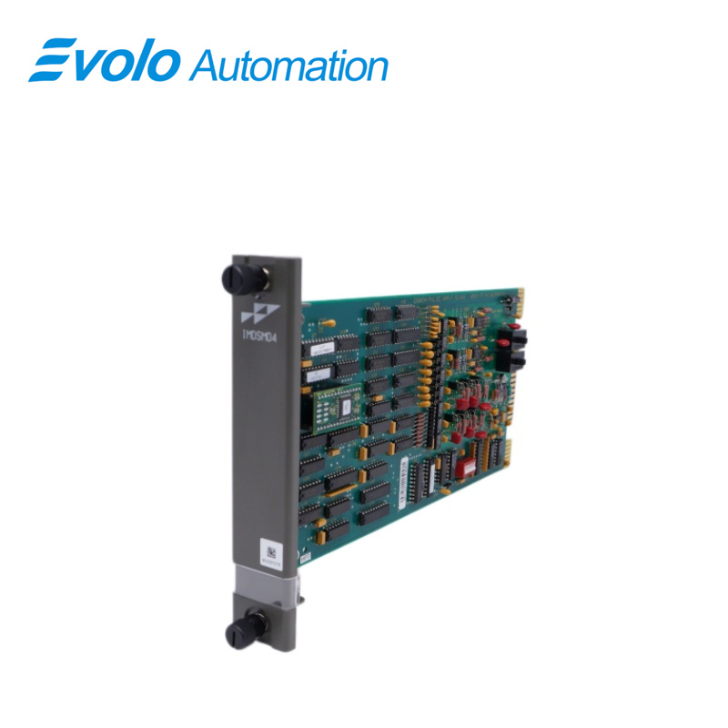
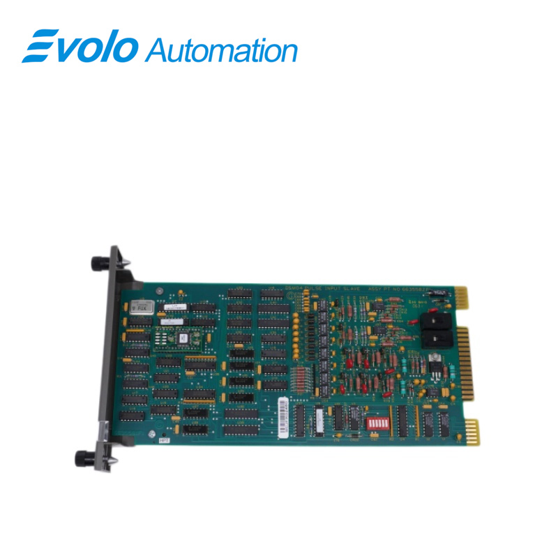
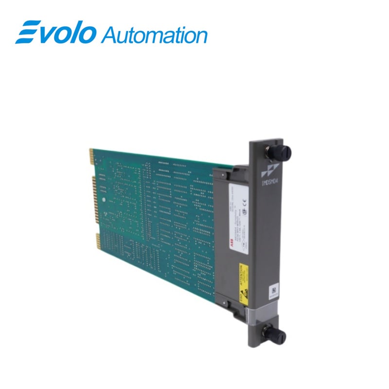
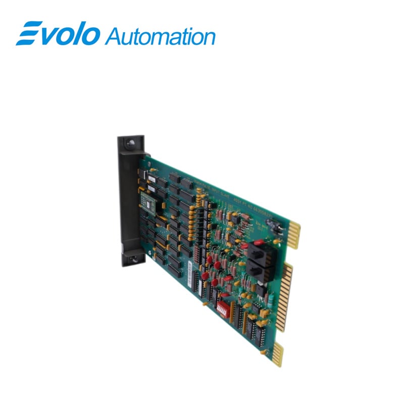
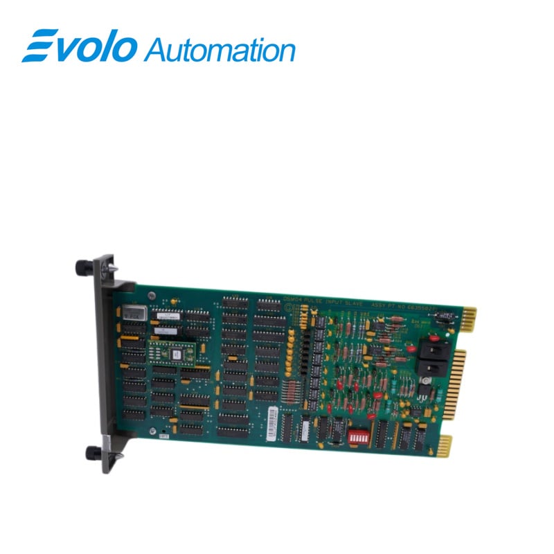
The IMDSM04 has a single printed circuit board that occupies one slot in a Module Mounting Unit (MMU). Two captive screws on the module faceplate secure the DSM to the MMU. The slave module has three card edge connectors for external signals and power. P1 connects to common (ground) and +5 VDC power. P2 connects the module to the slave expander bus to communicate with a master module (refer to Table 5-2). The pulse signals input through connector P3 using a cable connected to a Termination Unit (TU) or Termination Module (TM) (refer to Table 5-3). The terminal blocks (physical connection points) for field wiring are on the TU/TM. Each input can respond to either 4 to 6 VDC or 21.6 to 27 VDC and either the rising or falling edge of the signal. In addition, channels 1 and 2 can be routed through preamplifiers so they can respond to inputs from 50 mV (peak to peak) to 10 V (peak to peak).
The DSM set up information goes into an MFP using function codes. Use either a configuration tuning module or an operator interface unit. Function codes start the three modes of DSM operation. The three operating modes are: Totalize, Frequency, or Period.
Applications
1. Power Plants
This is the core of this module series:
Coal-fired power plants (coal, gas, biomass power generation)
Nuclear power plants (non-safety level conventional island control)
Cogeneration plants (providing urban heating and industrial steam)
Hydropower plants (unit speed regulation and monitoring)
2. Oil, Gas & Chemical Plants
Oil refineries (crude oil processing, cracking units)
Fertilizer plants (ammonia synthesis, urea production)
Natural gas processing plants and pressurization stations
Fine chemical plants (reactors and formulation control)
3. Heavy Manufacturing Plants
Paper mills and pulp mills (large paper machines, pulping production lines)
Steel mills and metallurgical plants (blast furnaces, coke ovens, continuous rolling production lines)
Cement plants (rotary kilns, mill control)
Mining and beneficiation plants (material conveying, crushing and filtration)
4. Municipal and Utility Plants
Large-scale wastewater treatment plants
Waterworks and pumping stations
Waste-to-energy plants
FEATURES
The IMDSM04 is a Pulse Input Auxiliary Module that supplies data to the Infi 90 Multi-Function Processor (MFP). The DSM conditions, converts and processes pulse inputs such as low level amplitude pulses, sinewaves, logic level pulses, or contact closures into digital signals. Applications for the DSM include: turbine flowmeters, tachometers, Wattmeters, proximity sensors and counters. One slave provides eight independent pulse or frequency inputs to the master module. The input signals are optically isolated. The DSM also Interfaces to existing Network 90 Multi-Function Controllers (MFCs). The modular design of the DSM, as with all Infi 90 modules, allows for flexibility when you are creating a process management system strategy. It can bring eight separate pulse signals in three voltage ranges. Two ranges are 4 to 6 VDC and 21.6 to 27 VDC (the 21.6 to 27 VDC range allows connection of dry contact inputs). The third range is input to the preamplifiers on channels 1 and 2 (for low level pulse inputs between 50 millivolts and 10 Volts peak to peak). The DSM connects inputs to the Infi 90 system without separate converters.
SPECIAL HANDLING
The Pulse Input Slave Module (DSM) uses electrostatic sensitive devices. Follow Steps 1 through 4 when handling:
1. Keep the module in its special anti-static bag until you are
ready to install it in the system. Save the bag for future use.
2. Ground the anti-static bag before opening.
3. Verify that all devices connected to the module are
grounded before using them.
4.Avoid touching the circuitry when handling the module.
REPAIR/REPLACEMENT
If the DSM is faulty, replace it with a new one. DO NOT try to repair the module; replacing components may affect the module performance. You can remove the module while system power is supplied. To replace a module:
1. Push and turn the two front panel captive retaining screws one half turn to unlatch the module. It is unlatched when the slots on the screws are vertical and the open end of the slots face away from the module.
2. Gently slide the module out of the MMU.
3. Configure the replacement module switch and jumper settings. Ensure they are set the same as the original module.
4. In the same slot assignment as the original module, align the replacement module with the plastic guide rails in the MMU. Gently slide it in until the front panel is flush with the top and bottom of the MMU frame.
5. Push and turn the two captive retaining screws on the module faceplate one half turn to the latched position. It is latched when the slots on the screws are vertical and the open ends face the center of the module. (To remove the module, turn the module retaining screws to the unlatched position and gently slide out).
6. Return to normal operation.
FAQ
Q: What is the IMDSM04?
A: It is a Pulse Input Auxiliary Module.
Q: What about your delivery time of IMDSM04?
A: Generally 1-3 days after receiving your payment. The specific delivery time depends on the type and quantity of the order.
Q: How long is the warranty period of IMDSM04?
A: We offer a standard one-year warranty for all new and original products.
Q: Do you offer any discounts?
A: Yes! For discounts on IMDSM04, please contact John for the best offer.