EN




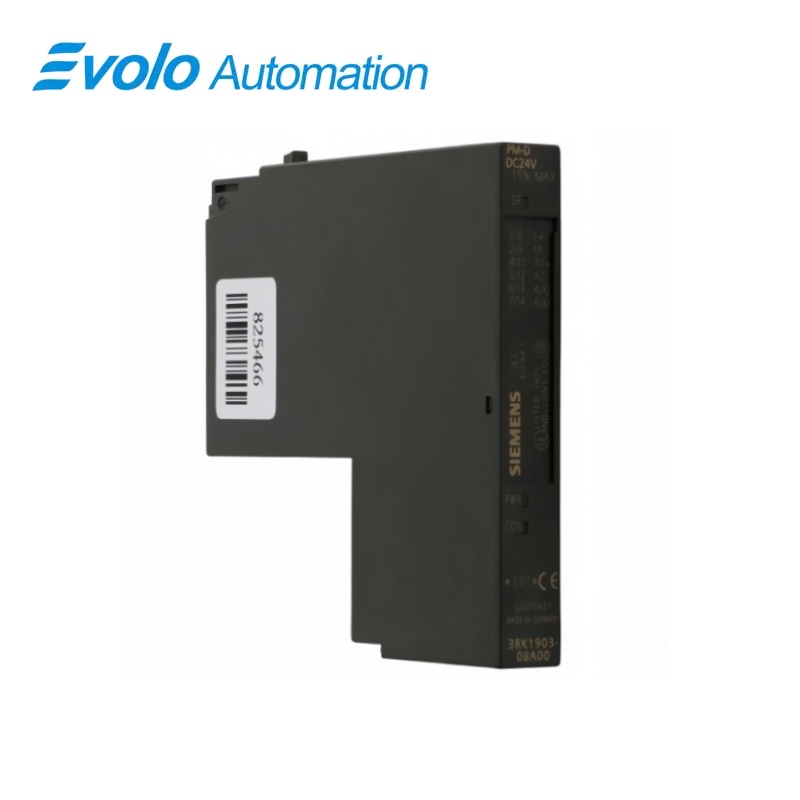
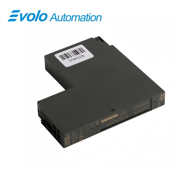
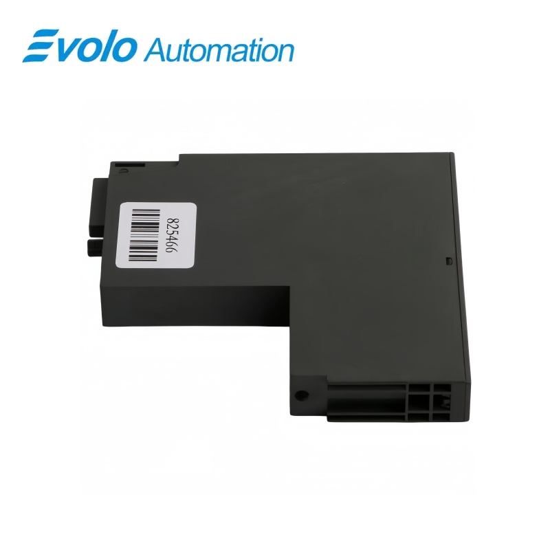
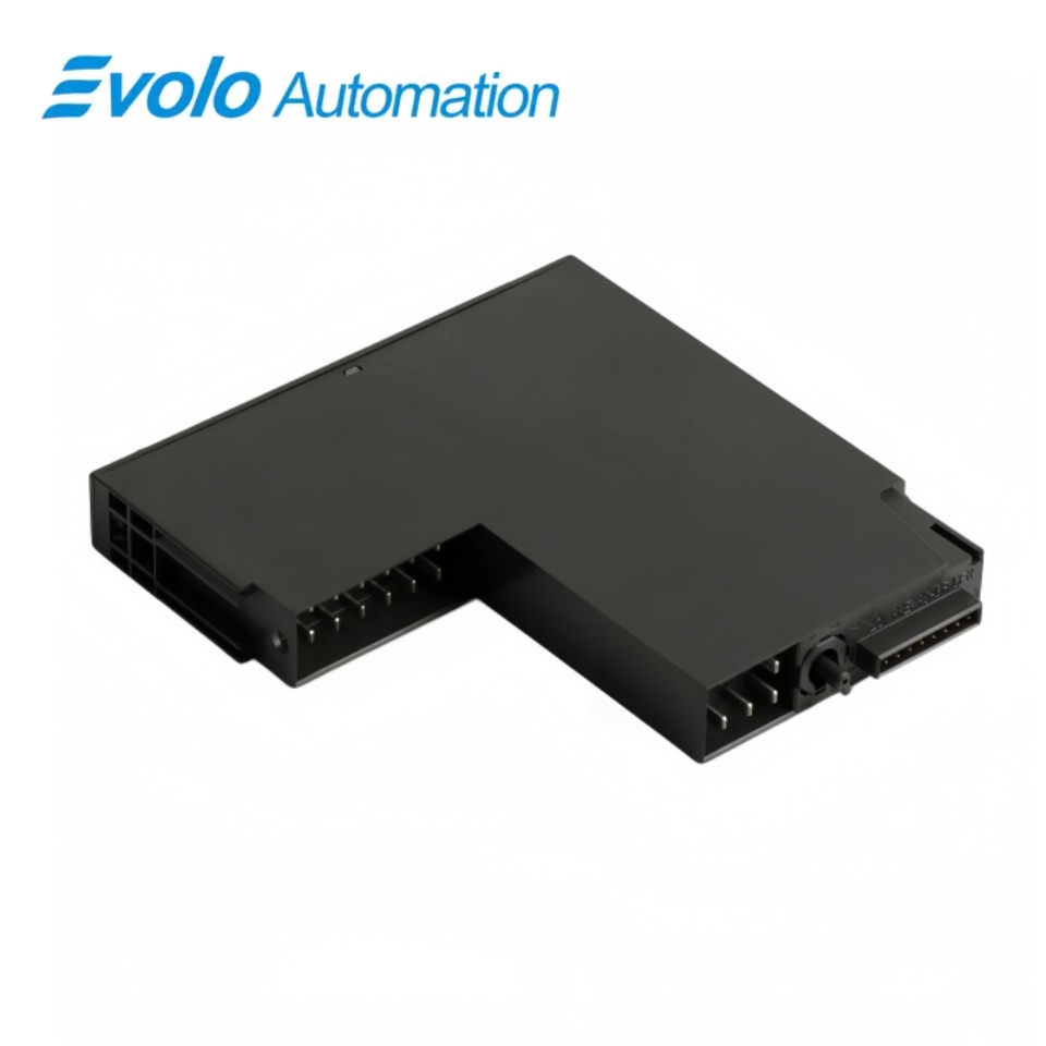
Siemens 3RK1903-0BA00 SIMATIC ET 200S PM-D 24V DC Power Module
Manufacturer: Siemens
Condition: Brand New
Lead Time: In Stock
Origin: Germany
Warranty: 12 Months
Email: [email protected]
whatsApp: +86-18150117685
- Overview
- Hot Selling Models
- Recommended Products
Overview
- Use the TM-P15 S27-01 terminal module, article 3RK1903-0AA00, for the PM-D assembly.
- Position the connected motor starters to the right of the power module in the same potential group.
- Keep both DC supply circuits within 20.4–28.8 V and provide the specified upstream protection.
- Enable group diagnosis when bus reporting and the SF fault indication are required.
- For High Feature AB4 starter installations, account for the common U1 supply or user-program reparameterization requirement.
- Disconnect the affected supply before inserting or removing the power module.
3RK1903-0BA00 SIMATIC ET 200S PM-D 24V DC Power Module
A PM-D power module that starts a new potential group and monitors the separate electronics and contactor supplies through PWR, CON and group diagnostics.
At a Glance
| Brand | Siemens |
|---|---|
| Model | 3RK1903-0BA00 |
| Product Type | PM-D power module |
| Core Function | Supplying and monitoring a motor-starter potential group |
| Application | ET 200S motor starters and frequency converters |
Two monitored supplies
U1 supplies the electronics and U2 supplies the contactors.
Local and bus diagnostics
PWR and CON indicate the supplies, while enabled group diagnostics report failures to the controller.
Matching terminal base
The PM-D plugs onto the TM-P15 S27-01 terminal module.
Product Overview
3RK1903-0BA00 starts an ET 200S motor-starter potential group with its associated terminal base and distributes the electronics and contactor supply voltages to the motor starters on its right.
The module monitors the U1 electronics supply and U2 contactor supply separately, with local indicators and optional group diagnostic messages for supply failures.
Key Functions
Monitor both control-voltage paths
The PWR indicator monitors U1 and the CON indicator monitors U2, helping separate an electronics-supply interruption from a missing contactor supply.
Report failures through enabled group diagnostics
Group diagnosis can be enabled at module level to transmit diagnostic messages; disabling it also suppresses the SF fault indication.
Begin a new motor-starter potential group
The power module and its terminal module form the start of the group, with the connected motor starters positioned to the right.
Official Specifications
| Rated Electronics and Contactor Supply | 24 V DC |
|---|---|
| Permissible DC Supply Range | 20.4–28.8 V |
| Rated Operating Current | 10 A |
| Backplane-Bus Current Draw | Maximum 10 mA |
| U1-to-U2 Insulation Test Voltage | 500 V |
| Supply and Fault Indicators | Green PWR for U1; green CON for U2; red SF for group error |
| Group-Diagnosis Parameter | Enable or Disable; factory setting Disable |
| Mounting Method and Position | Pluggable on terminal module; horizontal or vertical installation |
| Assembly Dimensions (Width × Height × Depth) | 15 × 196.5 × 117.5 mm, including terminal module |
| Operating Ambient Temperature | 0 to +60 °C |
| Storage and Transport Temperature | −40 to +70 °C |
| Relative Humidity During Operation | 5–95% |
| Maximum Installation Altitude | 2000 m above sea level |
| Front Protection | IP20; finger-safe to IEC 60529 |
| Mechanical Resistance | Shock: 5 g for 11 ms; vibration: 2 g |
| Net Module Weight | 53 g |
Frequently Asked Questions
Why can the SF light stay dark on 3RK1903-0BA00 even when a supply fault is present?
Disabling group diagnosis also suppresses fault display on the SF LED.
Which supply should I inspect when the CON indication on 3RK1903-0BA00 is missing?
The CON indicator corresponds to the U2 contactor supply, while PWR corresponds to the U1 electronics supply.
Can I exchange 3RK1903-0BA00 while the station is operating?
The power module must not be inserted or removed during operation.
Where do the motor starters sit relative to 3RK1903-0BA00?
The motor starters belonging to the potential group are connected to the right of its power module.
Can 3RK1903-0BA00 supply ordinary ET 200S electronic modules as well as motor starters?
The PM-D supplies the supported motor starters and frequency converters rather than ordinary electronic modules or Ex-i modules.
How should I arrange U1 when using 3RK1903-0BA00 with High Feature starters ending in AB4?
For AB4 starters using extended startup data outside GSD or GSDML integration, supply U1 from the same voltage source as the interface module or provide reparameterization in the user program.
Which upstream protection is recommended for 3RK1903-0BA00?
Use a 10 A gL/gG fuse or a 10 A circuit breaker with trip characteristic B.