EN
EN




- Overview
- Specifications
- Description
- Application Areas
- VOLTAGE AND CURRENT FEEDBACK VCO CIRCUITS
- POWER SUPPLIES
- FREQUENTLY ASKED QUESTIONS
- Recommended Products
Overview
Place of Origin: |
USA |
Brand Name: |
GE |
Model Number: |
DS200DCFBG1BLC |
Packaging Details: |
Original new Factory Sealed |
Delivery Time: |
5-7 days |
Payment Terms: |
T/T |
Supply Ability: |
In stock |
Specifications
|
Part Number |
DS200DCFBG1BLC |
|
Manufacturer |
General Electric |
|
Series |
EX2000 |
|
Product Type |
DC Power Supply Feedback Board |
|
Input Voltage |
100–240V AC, 50/60 Hz |
|
Output Voltage |
5 V / 12 V / 24 V DC |
|
Output Power |
50 W / 100 W / 250 W |
|
Ripple & Noise |
≤50 mV |
|
Efficiency |
≥85% |
|
Operating Temperature |
-10°C to +70°C |
|
Storage Temperature |
-40°C to +85°C |
|
Dimensions |
100 × 80 × 40 mm |
|
Protection Class |
IP67 |
|
Number of Digital Outputs |
16-channel digital outputs |
|
Output Type |
Relay output |
|
Mounting Method |
35 mm DIN rail mounting |
Description
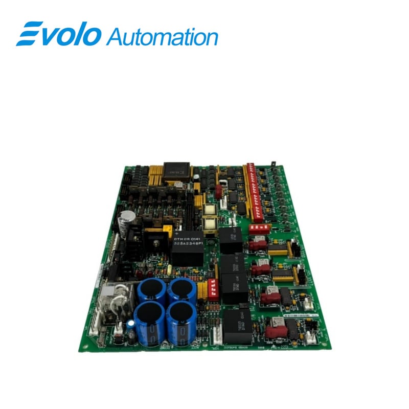
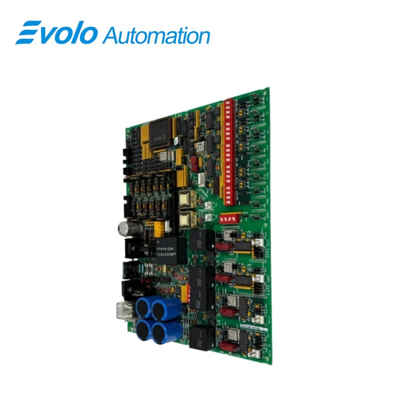
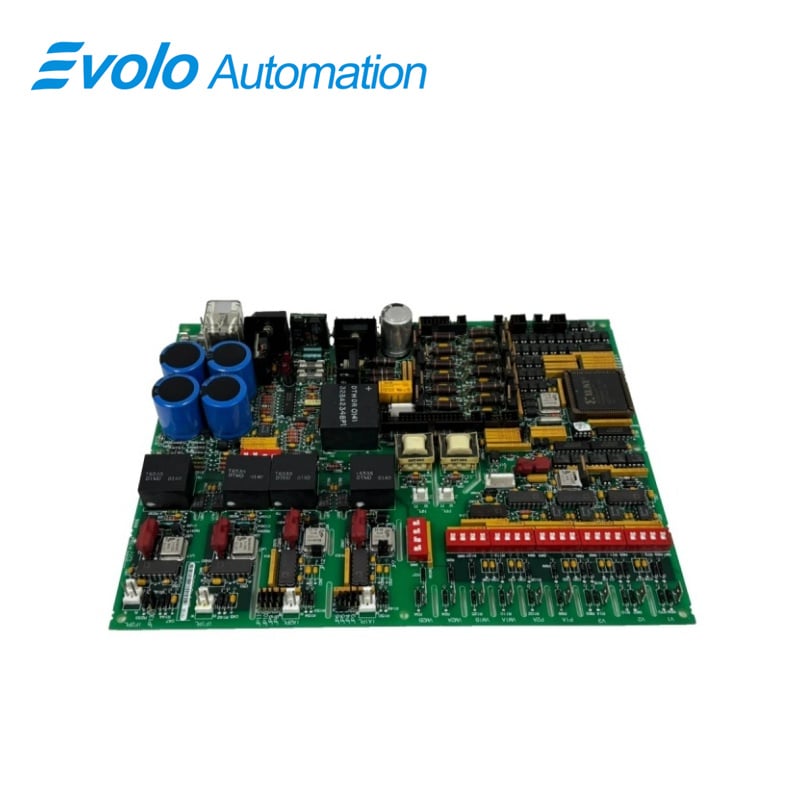
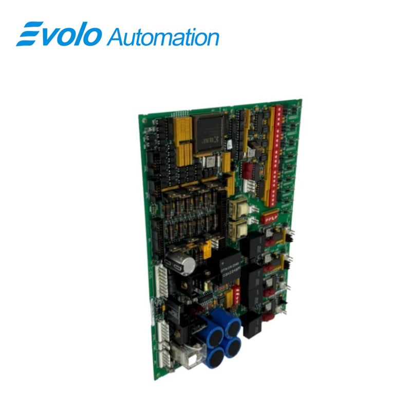
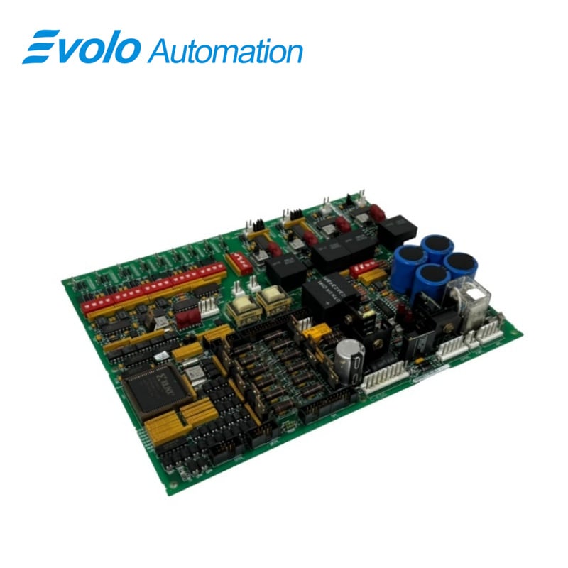
DS200DCFBG1BLC is a DC Power Supply Feedback Board manufactured and designed by General Electric used in EX2000, DC2000, CB2000, FC2000, GF2000, ME2000, and AC2000, IGBT drive applications.The EX2000 uses the board for a different purpose than the drive does.The Power Supply Board (DCFB) receives 38 and 115 V ac (24 V dc) input power from the control power transformer (CPT), and provides control-level power to the drive and 115 V ac power (NA) to the enclosure fans.The DCFB board includes the following circuits:
Control level power supplies(+5,+/-15 and +/-24VDC
Motor field power circuits (Except the SCR Module]
Driver circuits for the motor field SCR gate pulse generators.
Application Areas
This module is widely used in industrial automation, power systems, process control, manufacturing, railway and traffic control, and other fields. Specific applications include:
Powering the excitation circuit in an excitation system.
Generator voltage regulation.
Driver system control.
Industrial automation control systems.
VOLTAGE AND CURRENT FEEDBACK VCO CIRCUITS
The DCFB board includes voltage-controlled oscillator (VcO) circuits that convert input voltages to frequency signals. Each VCO has a nominal output frequency of 250 kHz.The output frequency varies from 0 to 500 kHz.depending upon the input voltaae. VCO outouts are sent to the SDcc/1 Dcc board throuah connector 1PLto provid feedback on the following:
SCR bridge ac input voltage
Output bridge voltage
Motor voltage (NA)
Millivolt signals from field shunts
Millivolt signals from armature shunts
The output bridge VCO circuit provides feedback to the SDCC/LDCC board through connector 1PL, pin 13(1PL-13).DIP switch SW4 is used to scale the voltage applied tc the circuit.A frequency-to-voltage reconstruction circuit provides a diagnostic signal for test point TP37 on the SDCC/LDCC board through 1PL-37.The diagnostic bridge voltage signal can be viewed using an AC-coupled oscilloscope.The second VCO provides feedback on the motor voltage to the SDCC/LDCC board through 1PL-39.DIl switch SW5 is used to scale the voltage applied to the circuit.
POWER SUPPLIES
The DCFB board receives 38 V ac(±10%) from the CPT(24 V dc).This voltage is full-wave rectified and filtered to produce the unregulated ±24 V dc outputs.The +24V dc output is rated at 3 A and the -24 V dc output is rated at 1 A.Regulators on the DCFB board derive ±15 V dc from the ±24 V dc supplies.The ±15 V dc outputs are each rated at 0.8 A, of which 0.25 A is available for external loading.The DCFB board also generates a +5 V dc, 4 A output from the +24 V dc supply.The /PSEN signal on 2PL goes to a TTL low state when the +5 V dc supply is in regulation and the signal goes high if the +5 V dc supply goes out of regulation.When high, /PSEN generates a micro-processor reset on the Drive Control Card(SDCC/LDCC)
The DCFB board provides isolated +5 and ±15 V dc supplies to power the armature current feedback circuits.The power supply outputs are protected against short circuits by fuses FU2 and FU3(7 A, 2AG).Light-emitting diodes (LEDs) CR51 and CR55 provide blown fuse indications for these fuses.The 115 V ac output is protected by fuse FU1(1/2 A, 2AG).Neon light LT1 provides a blown fuse indication for FU1.
FREQUENTLY ASKED QUESTIONS
What is the significance of bandwidth in a feedback control system about DS200DCFBG1BLC?
Bandwidth in a feedback control system determines how quickly the power supply can respond to changes in load or input voltage. A higher bandwidth allows for faster response times but can also introduce stability issues if not properly compensated. On the other hand, a lower bandwidth results in a slower response but ensures greater stability.
What is loop compensation in a DC power supply feedback system about DS200DCFBG1BLC?
Loop compensation is a technique used to stabilize the feedback system in a DC power supply, preventing oscillations and ensuring smooth regulation. It involves adding compensating components, such as resistors and capacitors, to the feedback loop to control the phase and gain response,
What role do operational amplifiers (op-amps) play in a feedback board about DS200DCFBG1BLC?
Operational amplifiers (op-amps) are a crucial component in feedback boards, primarily used for signal amplification and error detection. They compare the output voltage or current with the reference signal and generate an error voltage based on the difference