EN
EN




- Overview
- Specifications
- Description
- Applications
- Installation and Safety
- Maintenance and Troubleshooting
- FAQ
- Recommended Products
Overview
Place of Origin: |
USA |
Brand Name: |
GE |
Model Number: |
531X305NTBACG1 |
Packaging Details: |
Original new Factory Sealed |
Delivery Time: |
5-7 days |
Payment Terms: |
T/T |
Supply Ability: |
In stock |
Specifications
|
Product Name |
531X305NTBACG1 |
|
Type |
Terminal Board |
|
Dimensions |
28.8x7.7x2.4 cm |
|
Weight |
0.3 kg |
|
Power Supply Outputs (Regulated) |
5 VDC; 15 VDC |
|
Power Supply Outputs (Unregulated) |
24 VDC; 120 VAC |
|
Encoder Interface |
Supports 5 V and 15 V encoder configurations |
|
Relay Outputs |
7 channels total |
|
Relay Contact Rating |
120 VAC / 1 A |
|
Relay Types |
Form C and Form A combination |
|
Analog I/O |
Low-level analog input/output supported |
|
Adjustment Controls |
4 onboard potentiometers for scaling adjustment |
Description
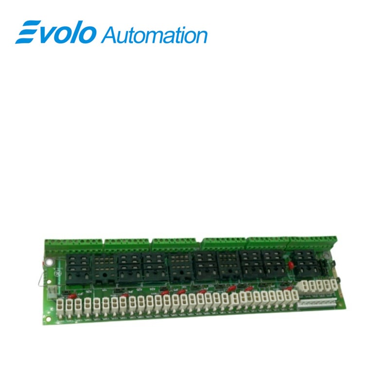
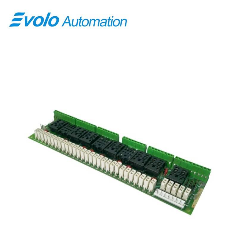
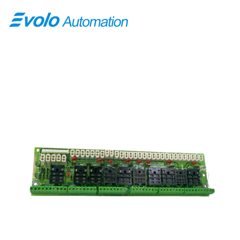
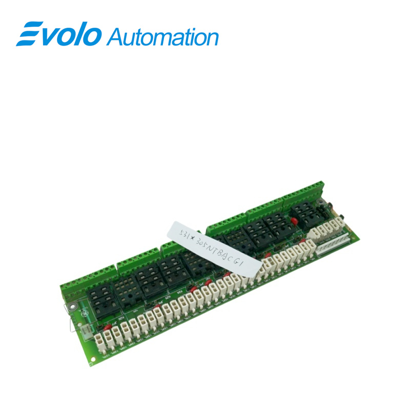
General Electric developed the 531X305NTBACG1 card as an NTB/3TB terminal board. This card was developed for the 531X series of replacement drive boards. A number of integral board features are provided by this board. Some of the interfaces included on the board include power supplies, encoders, analog I/O, relay outputs, and serial outputs. The NTB/3TB terminal card provides the drive with a number of important board features.
Applications
Steel Rolling Mill: Distributes encoder signals for accurate motor speed synchronization.
Heavy Machinery Plant: Controls actuator interlocks through relay outputs.
Paper & Printing Plant: Adjusts tension signals for stable paper handling.
Automated Assembly Plant: Powers sensors and small logic devices in control systems.
Mining Processing Plant: Supports safety alarms and emergency stop control.
Installation and Safety
Must follow manufacturer installation guidelines strictly
Recommended for use by qualified technical personnel only
Improper installation may affect overall drive system reliability
Maintenance and Troubleshooting
Troubleshooting: If the encoder feedback is abnormal, first check if the 5VDC/15VDC regulated output meets the standard; if the relay does not operate, check if the load exceeds the rated contact current of 1A. Analog deviations can be quickly corrected using the onboard potentiometer.
Maintenance Recommendations: Regularly check the tightness of the wiring at the screw terminals to prevent voltage output interruption due to industrial vibration. When cleaning the board, carefully avoid the potentiometer to prevent accidental changes to the original scaling ratio.
FAQ
Q: Can the 531X305NTBACG1 connect to both 5V and 15V encoders simultaneously?
A: This model supports both 5V and 15V encoder configurations, offering flexible sensor compatibility.
Q: What parameters are the four onboard potentiometers on the 531X305NTBACG1 primarily used to adjust?
A: They are used for scaling low-level analog I/O and field calibration of feedback signals.
Q: What is the purpose of the 120VAC unregulated output provided by the 531X305NTBACG1?
A: It supplies power for the 7 onboard relays and related AC control circuits.
Q: How can I determine if a relay channel on the 531X305NTBACG1 is faulty?
A: Check contact status or measure coil voltage; overload beyond 120 VAC / 1 A may damage contacts.
Q: When replacing the 531X305NTBACG1, is it necessary to record the potentiometer position?
A: Yes. Potentiometer settings affect signal scaling, so original values should be recorded for accurate replacement.