EN
EN




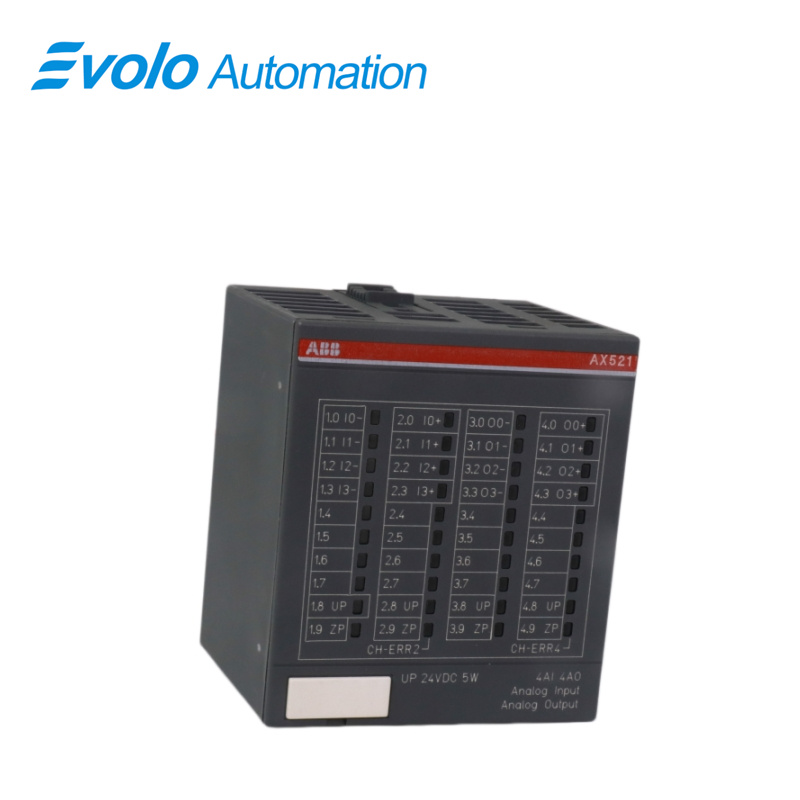
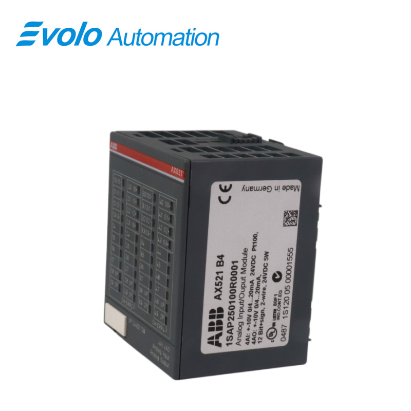
- Overview
- Specifications
- Description
- Applications
- Elements
- Features
- Functionality
- Electrical connection
- FAQ
- Recommended Products
Overview
Place of Origin: |
Sweden |
Brand Name: |
ABB |
Model Number: |
AX521 |
Packaging Details: |
Original new Factory Sealed |
Delivery Time: |
5-7 days |
Payment Terms: |
T/T |
Supply Ability: |
In stock |
Specifications
|
Model: |
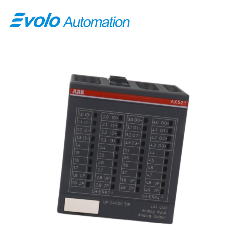
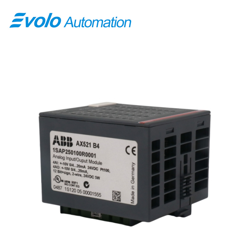
AX521 S500 Analog Input/Output Module |
|
Dimensions: |
6.8 x 6.3 x 7.7 cm |
|
Weight: |
0.14 kg |
|
Degree of Protection: |
IP00 |
|
WEEE Category: |
Product Not in WEEE Scope |
|
Analog Inputs: |
4 AI: U, I, RTD |
|
Analog Outputs: |
4 AO: U, I, 1-wire |
|
Input Type: |
Bipolar (not with current or Pt100/Pt1000/Ni1000) |
|
Electrical Isolation: |
Against internal supply and other modules |
|
Input Configurability: |
0...10 V, -10...+10 V, 0/4...20 mA, Pt100/Pt1000, Ni1000 (each input configurable individually) |
|
Channel Input Resistance: |
Voltage: >100 kΩ, Current: ~330 Ω |
|
Input Filter Time Constant: |
Voltage 100 µs, Current 100 µs |
|
Signal Indication: |
1 LED per channel |
|
Conversion Cycle: |
2 ms (for 8 inputs + 8 outputs), with Pt/Ni: 1 s |
|
Resolution: |
0...10 V: 12 bits; -10...+10 V: 12 bits + sign; 0...20 mA: 12 bits; 4...20 mA: 12 bits |
|
Overvoltage Protection: |
Yes |
|
Temperature Accuracy: |
0.1 °C |
|
LED Displays: |
11 LEDs for signals and error messages |
|
Internal Power Supply: |
Through expansion bus interface (I/O-Bus) |
|
External Power Supply: |
Terminals ZP and UP (process voltage 24 V DC) |
|
Digital Inputs (bytes): |
0 |
|
Digital Outputs (bytes): |
0 |
|
Counter Input Data (words): |
4 |
|
Counter Output Data (words): |
4 |
|
Reference Potential for Inputs: |
Terminals 1.8 to 4.8 (ZP) |
|
Input Signal Delay: |
Typ. 8 ms, configurable 0.1–32 ms |
|
Input Signal Voltage: |
0-30 V...+5 V (Signal 0), +13–30 V (Signal 1) |
|
Output Type: |
Bipolar with voltage, unipolar with current |
|
Output Configurability: |
-10...+10 V, 0...20 mA, 4...20 mA (each output configurable individually; current outputs channels 0–3) |
|
Output Resistance (load): |
0–500 Ω (current output) |
|
Output Loadability (voltage): |
Max ±10 mA |
|
Output Signal Indication: |
1 LED per channel |
|
Output Resolution: |
12 bits (+ sign) |
|
Mounting Position: |
Horizontal or vertical with derating (output load reduced to 50% at 40 °C per group) |
|
Cooling: |
Natural convection; must not be hindered by ducts or other parts in cabinet |
Description
The analog input/output modules AX521 can be used as remote expansion modules at the
FBP Interface Module DC505-FBP, at the CS31 Bus Module DC551-CS31 or locally at an AC500 CPU. The modules are supplied with a process voltage of 24 V DC. The analog inputs and outputs are electrically isolated from the rest of the modules' electronics.
Applications
Automated factories: Used for real-time data acquisition from pressure, flow, and temperature sensors, and for regulating valve control.
Food and beverage plants: Suitable for level monitoring and frequency converter speed control in filling lines and pasteurization processes.
Pharmaceutical manufacturing plants: Responsible for analog signal transmission in cleanroom environment monitoring and precision reactor control.
Machinery manufacturing plants: Integrated into the control systems of OEM machinery (such as plastic machinery and packaging machines).
Water treatment plants: Used for pressure monitoring in pump stations, flow regulation of dosing pumps, and level control in tanks.
Logistics and warehousing plants: Plays a core role in sensor feedback and conveyor belt speed control in automated sorting systems.
Elements
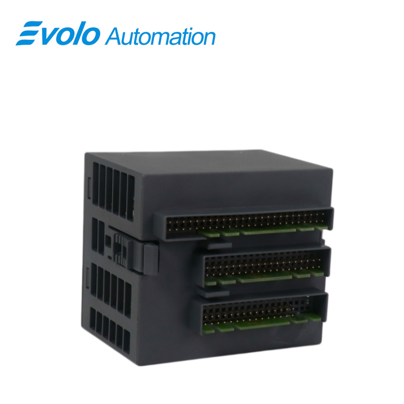
1 I/O-Bus
2 Allocation between terminal No. and signal name
3 4 yellow LEDs to display the signal statuses at the inputs I0 to I3 (AX521)
4 4 yellow LEDs to display the signal statuses at the outputs O0 to O3 (AX521)
5 8 yellow LEDs to display the signal statuses at the inputs I0 to I7 (AX522)
6 8 yellow LEDs to display the signal statuses at the outputs O0 to O7 (AX522)
7 1 green LED to display the process voltage UP
8 2 red LEDs to display errors (CH-ERR2 and CH-ERR4)
9 DIN rail
10 Label
11 I/O Terminal Unit (TU515/TU516) with 40 terminals (screw-type or spring terminals)
Features
4 configurable analog inputs in one group (1.0...2.3)
4 configurable analog outputs in one group (3.0...4.3)
Functionality
unused (default setting)
0...10
-10V...+10
0...20mA
4...20mA
Pt100,-50 °C...+400 °C(2-wire)
Pt100,-50 C...+400C(3-wire), requires 2 channels
Pt100,-50 °C...+70 °C (2-wire)
Pt100,-50 C...+70 °C (3-wire), requires 2 channels
Pt1000,-50°C...+400°C (2-wire)
Pt1000,-50°C...+400°C(3-wire), requires 2 channels
Ni1000,-50°C...+150°C(2-wire)
Ni1000,-50°C...+150 °C (3-wire),requires 2 channels
0...10 V with differential inputs, requires 2 channels
-10 V...+10 V with differential inputs, requires 2 channels
digital signals(digital input)
Electrical connection
The input/output modules are plugged on I/O Terminal Units TU515 or TU516. Properly seat the
modules and press until they lock in place. The Terminal Units are mounted on a DIN rail or with 2
screws plus the additional accessory for wall mounting (TA526). The electrical connection of the I/O channels is carried out using the 40 terminals of the I/O Terminal Unit. I/O modules can be replaced without re-wiring the Terminal Units.
FAQ
Q: What is the AX521?
A: It is a S500 Analog input/output module.
Q: Does the AX521 require a specific base?
A: Yes, it is typically mounted on a TU515 or TU516 terminal block.
Q: Is hot-swapping supported of AX521?
A: It is not recommended to plug or unplug electronic modules while the circuit is powered on, as this may damage the PLC baseboard or cause bus errors.
Q: What are the differences between the AX521-XC version?
A: The XC version (eXtreme Conditions) features an anti-corrosion coating, making it suitable for harsh environments with extreme temperatures, high altitudes, or corrosive gases.
Q: How to Check Price and Availability for AX521?
A: Please contact John Yang for sales at +86-18150117685 or request a quote.