EN
EN




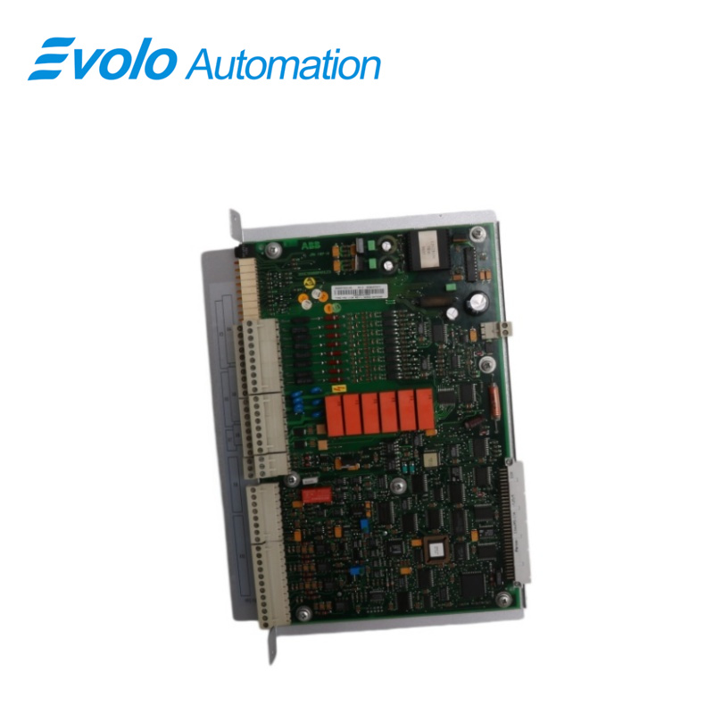
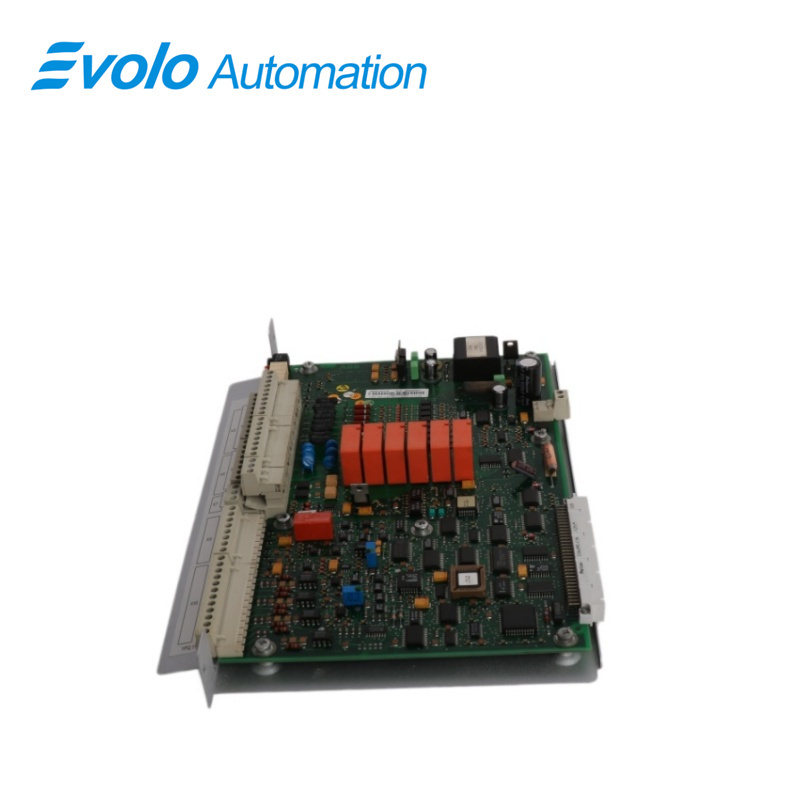
- Overview
- Specifications
- Description
- Applications
- Grounding
- Connections
- FAQ
- Recommended Products
Overview
Place of Origin: |
Sweden |
Brand Name: |
ABB |
Model Number: |
YPQ110A 3ASD573001A5 |
Packaging Details: |
Original new Factory Sealed |
Delivery Time: |
5-7 days |
Payment Terms: |
T/T |
Supply Ability: |
In stock |
Specifications
|
Parameter |
Value |
|
Model |
YPQ110A 3ASD573001A5 |
|
Type |
Extended I/O Board |
|
Analog Outputs - Channels |
2 |
|
Analog Output Voltage |
±10 V |
|
Analog Output Current |
±10 mA |
|
Resolution |
12 bits + sign |
|
Gain Error (0-70°C) |
typ < ±0.1%, max ±0.2% |
|
Offset Error (0-70°C) |
max ±0.5 mV |
|
Update Rate |
0.5 ms |
|
Reference Output +10 V |
Error: typ < ±1 mV, max ±3 mV, Output Current: ±10 mA |
|
Reference Output -10 V |
Error: typ < ±5 mV, max ±11 mV, Output Current: ±10 mA |
|
Current Reference 5 mA |
Error ±0.05 mA |
|
Load Resistance |
Max 1 kΩ |
|
Supply Voltage |
19 V min, 30 V max |
|
Power Consumption |
12 VA (0.5 A at 24 V) |
|
Low Speed Serial Bus |
Type: RS-485 isolated, Isolation Voltage: 60 V, Speed: 19200 baud, Max Bus Length: 300 m |
|
Digital Inputs - Channels |
8 |
|
Digital Inputs Nominal Voltage |
24 V AC/DC or 110 V AC/DC |
|
Digital Inputs Maximum Voltage |
30 V / 140 V |
|
Digital Inputs Impedance |
3 kΩ / 13 kΩ |
|
Digital Input Voltage Levels |
Low max 4 V / 11 V, High min 18 V / 90 V, Threshold typ 13 V / 50 V |
|
Digital Input Isolation Voltage |
1500 V |
|
Digital Input Hardware Delay |
2 ms |
|
Digital Filter Time |
0.5 ms to 128 ms in 0.5 ms steps |
Description
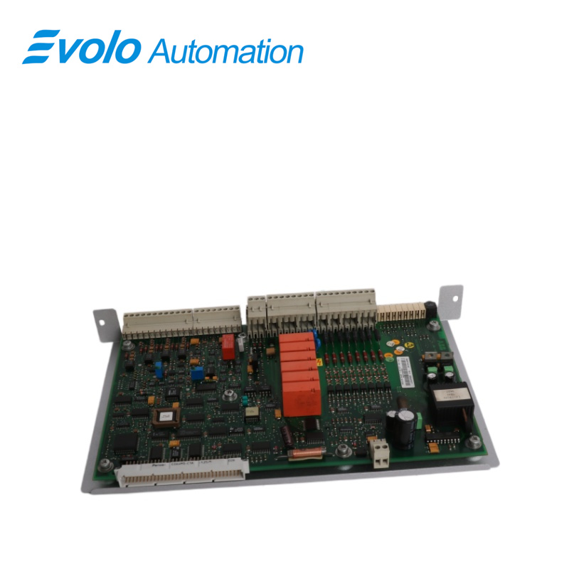
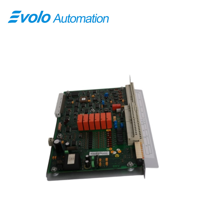
The I/O-board YPQ110A 3ASD573001A5 is mounted next to the application controller YPP110A or next to another I/O-board. It is connected to the I/O-bus with a 64 pole ribbon cable at X1 and also powered from it. X2 is not connected except for remote I/O, see below. The board address can be set to 0-15 (0-9,A-F) with the board address switch. A timeout period can be set by software. When the I/O board has not been updated with new data within the timeout period the outputs is reset. This is not implemented in the local I/O function elements but can be used with remote I/O.
Applications
Precision paper machine plant: Used to collect large amounts of tension and speed feedback signals and output control valve commands.
Metal foil rolling mill: Manages the monitoring of digital and analog signals for cooling systems and auxiliary hydraulic systems.
Large textile mill: Processes logic interlocking signals between different sections in multi-axis synchronous operation.
Rubber mixing plant: Monitors sensor data acquisition for batching, temperature, and mixing pressure.
Beverage packaging plant: Coordinates the actions of various limit switches and actuators on high-speed production lines.
Grounding
The 0 V on the I/O-board is connected to the rack unit housing the I/O board which shall be grounded in the cubicle with the four fastening screws at the back of the box. Analog I/O signals shall use screened cables with the screen connected to the row of holes at the front of the rack unit. This is necessary to get the best possible immunity to disturbances.
Connections
The remote I/O-board is connected to the low speed serial bus.The bus is a multi-drop configuration. Star connection is not allowed. A screened cable with two twisted pairs shall be used. The cable shall be terminated at both ends. The master end, normally at an APC, has an active termination and the last device on the bus has a passive termination.
FAQ
Q: Is the YPQ110A 3ASD573001A5 a motherboard or an expansion board?
A: It is an expansion I/O board to add physical signal interfaces, not the main CPU executing control logic.
Q: Can the YPQ110A 3ASD573001A5 be hot-swapped?
A: No. Removing it while powered causes electrical spikes on the backplane bus, potentially damaging the board or adjacent processors.
Q: Why do paper machine factories need multiple YPQ110A 3ASD573001A5 boards?
A: Paper lines are long, with hundreds or thousands of limit switches, pressure transmitters, and control valves. Multiple boards ensure full data coverage.
Q: How can I determine if the problem is with a sensor or a YPQ110A 3ASD573001A5 channel?
A: Measure voltage at the input terminals. If there is input but software shows no change, the board channel is faulty; otherwise, it’s external wiring.
Q: What do the LED indicators on the YPQ110A 3ASD573001A5 represent?
A: Green indicates normal power; red indicates self-test failure or abnormal bus communication.