EN
EN




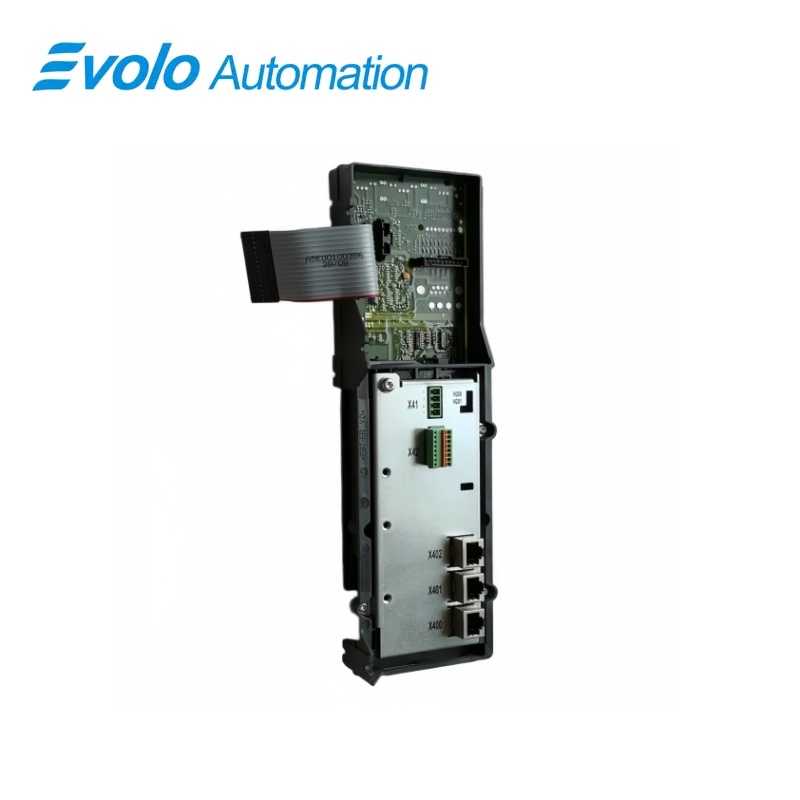
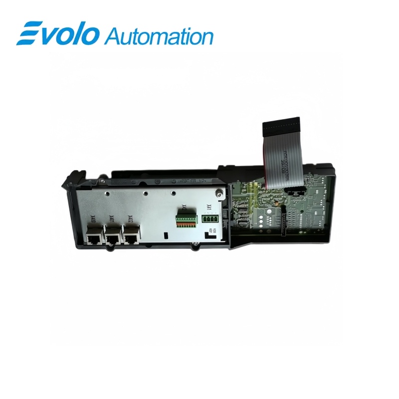
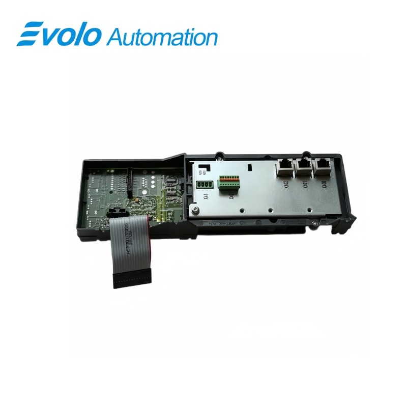
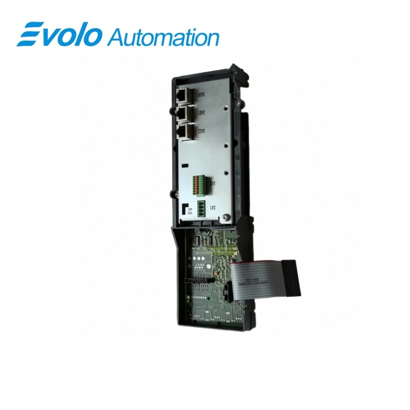
Siemens SINAMICS S Replacement Control Interface Board for 1200 A Smart Line Module 6SL3353-6TG41-2CA3
Manufacturer: Siemens
Condition: Brand New
Lead Time: In Stock
Origin: Germany
Warranty: 12 Months
Email: [email protected]
whatsApp: +86-18150117685
- Overview
- Product Overview
- Key Functions
- Official Specifications
- Frequently Asked Questions
- Compatibility & Ordering Notes
- Hot Selling Models
- Recommended Products
Overview
SIEMENS · SINAMICS S
6SL3353-6TG41-2CA3 SINAMICS S Replacement Control Interface Board for 1200 A Smart Line Module
This Siemens replacement Control Interface Board is assigned to a 1200 A chassis-format Smart Line Module operating from a 500 to 690 V three-phase supply at 50 or 60 Hz.
At a Glance
| Brand | Siemens |
|---|---|
| Model | 6SL3353-6TG41-2CA3 |
| Product Type | replacement control interface board |
| Core Function | Provides control communication and LED diagnostics for a chassis-format Smart Line Module |
| Application or Compatible Series | SINAMICS S chassis Smart Line Modules equipped with the classic control interface board |
Exact Identification
Match 6SL3353-6TG41-2CA3 character by character and confirm the complete SINAMICS S Replacement Control Interface Board for 1200 A Smart Line Module designation.
Interface Arrangement
Confirm the installed supply, ports, field connections and required accessories before wiring the replacement.
Configuration Check
Preserve the approved engineering project, network parameters and application data used by the installed system.
Product Overview
This Siemens replacement Control Interface Board is assigned to a 1200 A chassis-format Smart Line Module operating from a 500 to 690 V three-phase supply at 50 or 60 Hz.
The board forms the control interface for the specified chassis-format Smart Line Module and participates in cyclic DRIVE-CLiQ communication. READY and DC LINK indicators identify supply, communication, operating and fault states during commissioning and service. Defined flashing patterns show firmware download progress and permit component identification through parameter p0124.
Key Functions
Smart Line Module Control
The board forms the control interface for the specified chassis-format Smart Line Module and participates in cyclic DRIVE-CLiQ communication.
Operating-State Diagnostics
READY and DC LINK indicators identify supply, communication, operating and fault states during commissioning and service.
Firmware and Component Identification
Defined flashing patterns show firmware download progress and permit component identification through parameter p0124.
Official Specifications
| Host Line-Supply Range | 500 to 690 V, three-phase AC |
|---|---|
| Host Line Frequency | 50 or 60 Hz |
| Host Rated Current | 1200 A |
| Net Weight | 0.4 kg |
| Diagnostic Indicators | READY and DC LINK LEDs |
| Electronic-Supply Diagnostic | Both LEDs off when the electronic power supply is missing or outside tolerance |
| Normal Communication State | READY green with cyclic DRIVE-CLiQ communication active |
| DC-Link Present State | READY green and DC LINK orange |
| DC-Link Overvoltage State | READY green and DC LINK red |
| Communication Establishment State | READY orange and DC LINK orange |
| Component Fault State | READY red |
| Firmware Download State | READY flashes green/red at 0.5 Hz |
| Firmware Download Complete State | READY flashes green/red at 2 Hz; POWER ON is then required |
| LED Component Identification | Green/orange or red/orange flashing at 2 Hz when p0124 is activated |
Frequently Asked Questions
Which Smart Line Module rating must match 6SL3353-6TG41-2CA3?
Use it with the 1200 A chassis-format Smart Line Module identified for a 500 to 690 V three-phase supply.
What does an orange READY indication mean on 6SL3353-6TG41-2CA3?
An orange READY indication together with an orange DC LINK indication means that DRIVE-CLiQ communication is being established.
How can I recognize a firmware download on 6SL3353-6TG41-2CA3?
The READY indicator flashes green and red at 0.5 Hz while firmware is being downloaded.
What should I do when 6SL3353-6TG41-2CA3 flashes green and red at 2 Hz?
Perform the required power cycle because that pattern indicates that the firmware download has completed.
Can the DC LINK indicator on 6SL3353-6TG41-2CA3 prove that the DC link is safe to touch?
No, hazardous DC-link voltage may still be present regardless of the indicator state, so the approved isolation procedure remains mandatory.
How is component identification activated for 6SL3353-6TG41-2CA3?
Activate parameter p0124 to produce the defined 2 Hz identification flashing pattern.
What should be checked before replacing 6SL3353-6TG41-2CA3?
Match the complete article number, host voltage and current rating, connector arrangement, firmware state and saved drive configuration before installation.
Compatibility & Ordering Notes
Compatibility Checklist
- Use the board only in the specified chassis-format Smart Line Module hardware arrangement.
- De-energize and verify the DC link according to the approved SINAMICS safety procedure before removal.
- Preserve the drive project and firmware information before exchanging the control interface board.