EN
EN




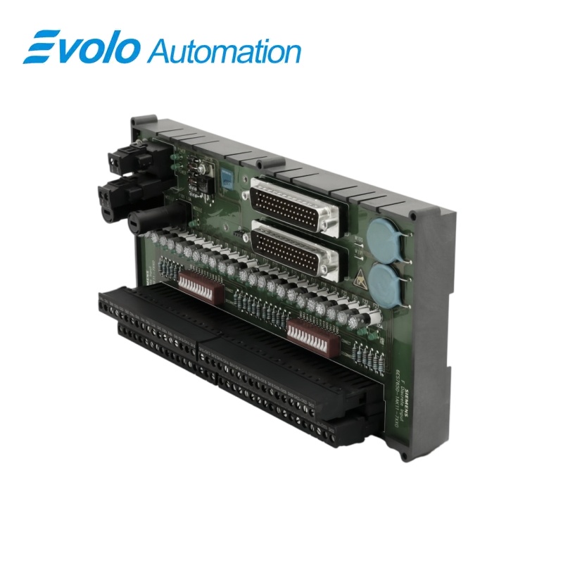
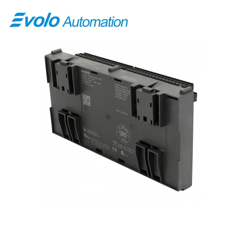
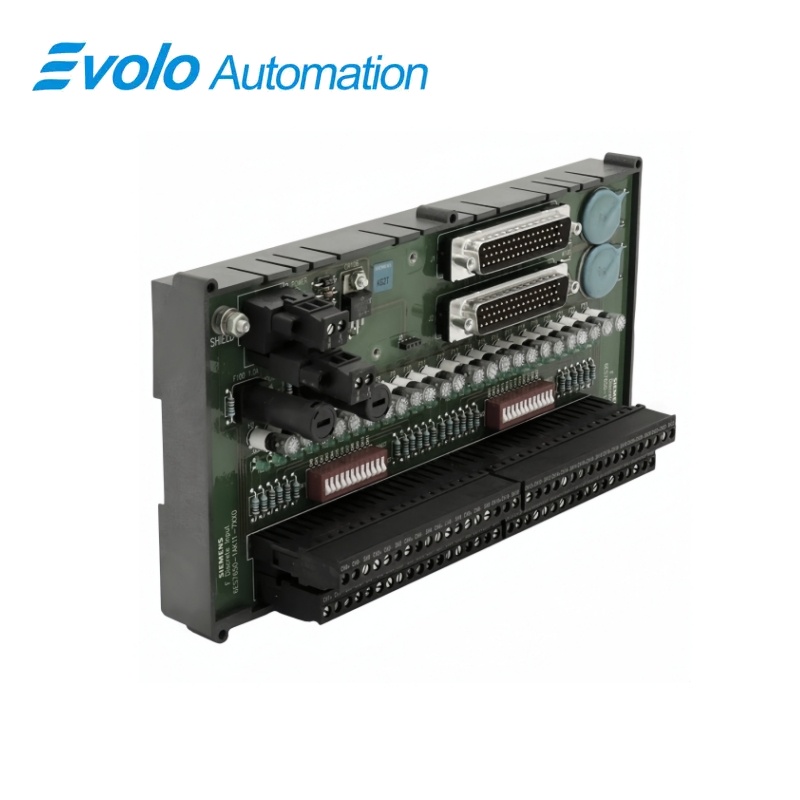
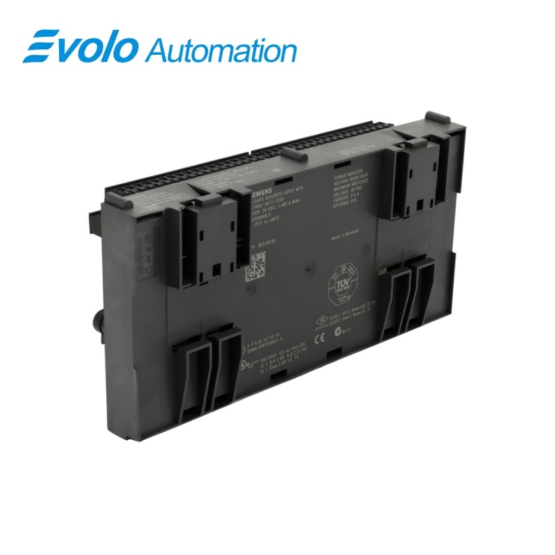
Siemens SIMATIC PCS 7 Redundant F-DI MTA Connection Module 6ES7650-1AK11-7XX0
Manufacturer: Siemens
Condition: Brand New
Lead Time: In Stock
Origin: Germany
Warranty: 12 Months
Email: [email protected]
whatsApp: +86-18150117685
- Overview
- Product Overview
- Key Functions
- Official Specifications
- Frequently Asked Questions
- Compatibility & Ordering Notes
- Hot Selling Models
- Recommended Products
Overview
Siemens • SIMATIC PCS 7
6ES7650-1AK11-7XX0 SIMATIC PCS 7 Redundant F-DI MTA Connection Module
The SIMATIC PCS 7 F-DI MTA is a redundant 12/24-channel 24 V DC marshalling assembly for fail-safe digital-input modules, with protected power distribution and channel indication.
At a Glance
| Brand | Siemens |
|---|---|
| Model | 6ES7650-1AK11-7XX0 |
| Product Type | Redundant fail-safe digital-input marshalling terminal assembly |
| Core Function | Marshals and protects redundant 24 V DC safety input channels |
| Application or Compatible Series | PCS 7 safety I/O using redundant 6ES7326-1BK02-0AB0 modules |
Exact Identification
Match 6ES7650-1AK11-7XX0 character by character and confirm the complete SIMATIC PCS 7 Redundant F-DI MTA Connection Module designation.
Interface Arrangement
Confirm the installed supply, ports, field connections and required accessories before wiring the replacement.
Configuration Check
Preserve the approved engineering project, network parameters and application data used by the installed system.
Product Overview
The SIMATIC PCS 7 F-DI MTA is a redundant 12/24-channel 24 V DC marshalling assembly for fail-safe digital-input modules, with protected power distribution and channel indication.
The assembly connects the specified redundant F-DI module arrangement for high-availability process safety applications. Individual channel protection and a protected module supply localize wiring and power faults. Green indicators show input power, module power and channel power conditions.
Key Functions
Redundant Safety I/O Connection
The assembly connects the specified redundant F-DI module arrangement for high-availability process safety applications.
Protected Channel Distribution
Individual channel protection and a protected module supply localize wiring and power faults.
Visible Power Status
Green indicators show input power, module power and channel power conditions.
Official Specifications
| I/O Capacity | 12 or 24 fail-safe digital input channels |
|---|---|
| Signal Voltage | 24 V DC |
| Compatible F-DI Module | 6ES7326-1BK02-0AB0 |
| Typical Power Dissipation | 3 W |
| Wire Size Range | 24 to 14 AWG |
| Metric Wire Size Range | 0.205 to 2.08 mm² |
| Individual Channel Fuse | 0.05 A |
| Module Power Fuse | 2.0 A |
| Status Indicators | Input power, module power and channel power LEDs |
| Indicator Color | Green |
| Horizontal Operating Temperature | -25 to 70 °C |
| Vertical Operating Temperature | -25 to 60 °C |
| Relative Humidity | 5% to 95%, non-condensing |
| 1oo1 Safety Capability | SIL 2, PL d, Category 3 |
| 1oo2 Safety Capability | SIL 3, PL e, Category 4 |
| Proof-Test Interval | 20 years |
Frequently Asked Questions
Which safety input module is compatible with 6ES7650-1AK11-7XX0?
Use it with the specified 24 V DC fail-safe digital-input module in the engineered redundant arrangement.
How many field channels can 6ES7650-1AK11-7XX0 marshal?
The assembly supports a 12-channel or 24-channel connection arrangement according to the selected wiring design.
What do the LEDs on 6ES7650-1AK11-7XX0 indicate?
The green indicators show the presence of input power, module power and channel power.
Can two redundant sensors share one channel on 6ES7650-1AK11-7XX0?
No; the published wiring restrictions do not permit two redundant sensors on a single channel.
What wire sizes can be terminated on 6ES7650-1AK11-7XX0?
Use conductors from 24 to 14 AWG, or 0.205 to 2.08 mm², with approved preparation.
What must be documented before replacing 6ES7650-1AK11-7XX0?
Record every terminal, channel fuse, power feed, redundant module assignment and safety-loop test result.
How should 6ES7650-1AK11-7XX0 be validated after installation?
Perform the approved proof test and verify power indication, channel states, diagnostics and every safety response.
Compatibility & Ordering Notes
Compatibility Checklist
- Use only with the specified fail-safe digital-input module and approved redundant wiring.
- Observe the restriction against two redundant sensors on one channel.
- Complete the validated safety proof test before returning the loop to service.