EN




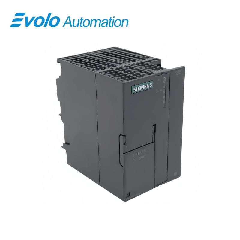
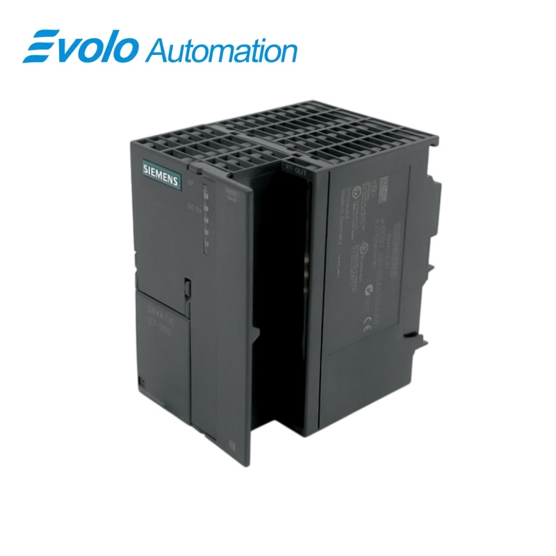
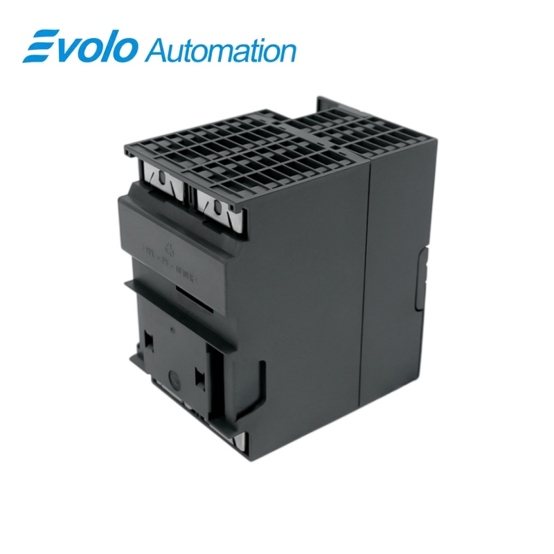
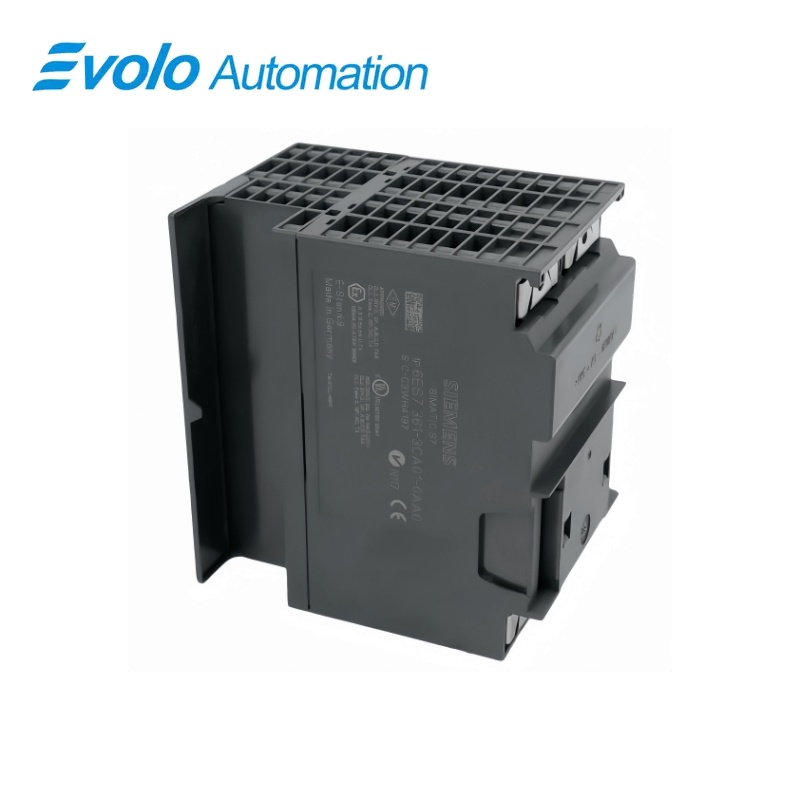
Siemens 6ES7361-3CA01-0AA0 SIMATIC S7-300 IM 361 Expansion Interface Module
Manufacturer: Siemens
Condition: Brand New
Lead Time: In Stock
Origin: Germany
Warranty: 12 Months
Email: [email protected]
whatsApp: +86-18150117685
- Overview
- Hot Selling Models
- Recommended Products
Overview
- Confirm the CPU permits expansion racks; CPU 312 and CPU 312C are single-rack types.
- Use IM 360 in the central rack and IM 361 in expansion racks 1–3.
- Place the interface in slot 3 before the first signal module.
- Keep every interface-to-interface cable link within 10 m.
- Check the separate 24 V supply and the 0.8 A backplane budget.
6ES7361-3CA01-0AA0 SIMATIC S7-300 IM 361 Expansion Interface Module
A 24 V DC IM 361 receiving interface for S7-300 expansion racks, with a maximum 10 m link to the next interface module.
At a Glance
| Brand | Siemens |
|---|---|
| Model | 6ES7361-3CA01-0AA0 |
| Product Type | Expansion-rack interface module |
| Core Function | Extending the controller backplane bus |
| Application | S7-300 expansion racks 1–3 |
Expansion-rack interface
IM 361 serves racks 1–3 in a compatible multi-rack S7-300 system.
Backplane supply
The interface provides up to 0.8 A to the expansion-rack backplane.
Local service indicators
SF and 5 V DC LEDs support connection and supply checks.
Product Overview
6ES7361-3CA01-0AA0 connects an S7-300 expansion rack to the central-rack IM 360 or another IM 361. It extends the backplane bus with communication-bus support and uses a separate 24 V DC supply.
The IM 360/IM 361 arrangement supports up to three expansion racks on compatible CPUs. Each link between successive interface modules may be up to 10 m, and the connected modules must remain within the expansion-rack backplane current budget.
Key Functions
Receive the rack-extension link
The interface connects an expansion rack to an IM 360 or an upstream IM 361.
Supply the expansion backplane
The 24 V-fed interface provides a maximum backplane current of 0.8 A.
Support service checks
The SF indicator reports group faults and the 5 V DC indicator shows the backplane supply.
Official Specifications
| Rated supply | 24 V DC |
|---|---|
| Maximum supply current | 500 mA |
| Typical power loss | 5 W |
| Maximum backplane current output | 0.8 A |
| Maximum link to the next interface module | 10 m |
| Maximum interfaces per CPU | 3 |
| Status and error indicators | SF group error and 5 V DC backplane-supply LEDs |
| Dimensions | 80 × 125 × 120 mm (W × H × D) |
| Approximate weight | 505 g |
Frequently Asked Questions
Which central-rack interface works with 6ES7361-3CA01-0AA0?
Use an IM 360 in the central rack for the IM 360/IM 361 expansion arrangement.
Which slot is assigned to 6ES7361-3CA01-0AA0?
The interface module occupies slot 3, to the left of the first signal module.
How many expansion racks can use 6ES7361-3CA01-0AA0?
The supported multi-rack arrangement permits up to three expansion racks.
Can I add expansion racks with 6ES7361-3CA01-0AA0 to a CPU 312 or CPU 312C?
CPU 312 and CPU 312C support only a single-rack configuration.
What is the maximum cable link to the next 6ES7361-3CA01-0AA0?
The maximum distance between successive interface modules is 10 m.
Which backplane-current limit should I check for 6ES7361-3CA01-0AA0?
The expansion-rack modules must remain within the 0.8 A backplane output limit.
What connection conditions can light the SF LED on 6ES7361-3CA01-0AA0?
A missing connecting cable, a switched-off downstream IM 361 or a powered-off CPU can light the SF indicator.