EN




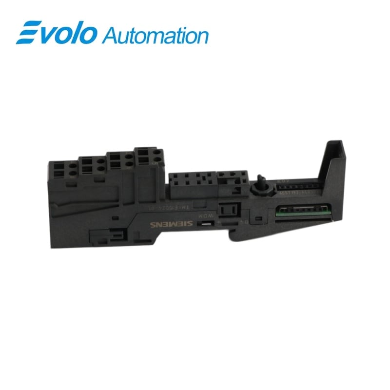
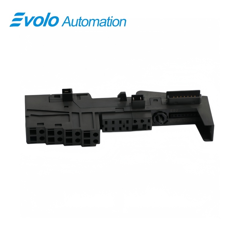
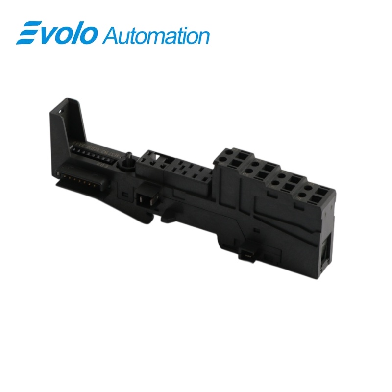
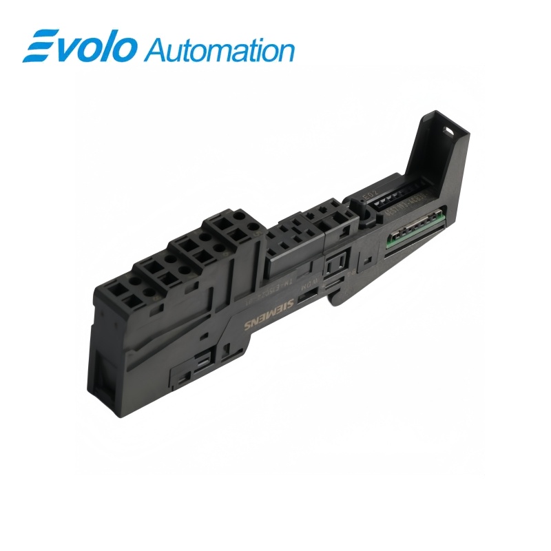
Siemens 6ES7193-4CA20-0AA0 SIMATIC ET 200S TM-E15S24-A1 Terminal Module
Manufacturer: Siemens
Condition: Brand New
Lead Time: In Stock
Origin: Germany
Warranty: 12 Months
Email: [email protected]
whatsApp: +86-18150117685
- Overview
- Hot Selling Models
- Recommended Products
Overview
- Use A4 and A8 only for the intended AUX1 connection.
- Match electronic signals to terminals 1–3 and 5–7.
- Keep the continuous auxiliary bus consistent across the station.
- Prepare 11 mm stripped ends and control the screw torque.
SIEMENS SIMATIC ET 200S
6ES7193-4CA20-0AA0 SIMATIC ET 200S TM-E15S24-A1 Terminal Module
A screw-terminal ET 200S electronic-module base with a continuous auxiliary bus accessible at A4 and A8.
At a Glance
| Brand | Siemens |
|---|---|
| Model | 6ES7193-4CA20-0AA0 |
| Product Type | Electronic module base |
| Core Function | Modular field termination |
| Application | ET 200S sensor and actuator wiring |
Screw-wired AUX1 access
The -A1 base makes the auxiliary bus available beside the electronic-module field connections.
Defined signal positions
Electronic module signals use terminals 1–3 and 5–7 in the two-column layout.
Prewired station assembly
Mount and wire the terminal base before inserting the corresponding electronic module.
Product Overview
6ES7193-4CA20-0AA0 provides the TM-E15S24-A1 screw-terminal foundation for 15 mm ET 200S electronic modules.
Its terminal pattern combines six positions assigned by the electronic module with A4 and A8 auxiliary connections, keeping AUX1 continuous through the station row.
Key Functions
Combine signal and auxiliary wiring
Numbered terminals 1–3 and 5–7 serve the inserted electronic module, with A4 and A8 reserved for AUX1.
Distribute the auxiliary potential
The continuous AUX1 bus passes to adjacent modules and can provide a protective-conductor or additional potential connection.
Prepare the cabinet wiring in advance
The base can be installed and wired without the electronics, keeping terminal work separate from module insertion.
Official Specifications
| Terminal arrangement | 2 × 4 connections |
|---|---|
| Connection technology | Screw terminals |
| AUX1 routing | Continuous to the potential group on the left |
| AUX1 terminal access | A4 and A8 |
| Bare solid and flexible conductor range | 0.14–2.5 mm² |
| Flexible conductor range with ferrule | 0.14–1.5 mm² |
| Wire stripping length | 11 mm |
| Conductors per connection | 1; alternatively 2 totaling up to 1.5 mm² in a shared ferrule |
| Maximum wire insulation diameter | 3.1 mm at 1.5 mm²; 3.8 mm at 2.5 mm² |
| Wiring tool | Screwdriver with 3 mm blade |
| Terminal tightening torque | 0.4–0.7 N·m |
| Dimensions (W × H × D) | 15 × 132 × 43 mm |
| Approximate module weight | 65 g |
Frequently Asked Questions
Can 6ES7193-4CA20-0AA0 combine electronic signals and a protective-conductor bus at one position?
Yes, the electronic module uses terminals 1–3 and 5–7 while A4 and A8 can provide the AUX1 protective-conductor connection.
Does 6ES7193-4CA20-0AA0 support Defined signal positions for mobile equipment?
No, the -A1 layout uses A4 and A8 for AUX1 instead of assigning all eight numbered positions to the electronic module.
What should I consider before applying an extra voltage to AUX1 on 6ES7193-4CA20-0AA0?
The selected auxiliary potential must suit the application and its continuity to the group on the left, with the bus limited to 230 V AC.
Is a 2.5 mm² bare conductor allowed on 6ES7193-4CA20-0AA0?
Yes, the screw terminals accept bare solid or flexible conductors from 0.14 to 2.5 mm².
How do I avoid overtightening the terminals of 6ES7193-4CA20-0AA0?
Use a torque-controlled 3 mm screwdriver set within the specified 0.4–0.7 N·m range.
Do I need the electronic module installed to wire 6ES7193-4CA20-0AA0?
No, the terminal module can be completely wired before inserting the matching electronics.
Should I disconnect adjacent wiring to change only the terminal box of 6ES7193-4CA20-0AA0?
The terminal box can be replaced without removing the terminal module from the rail, so base removal is not required for that operation.