EN




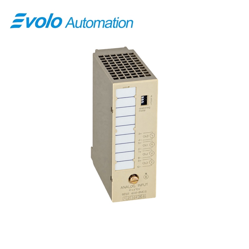
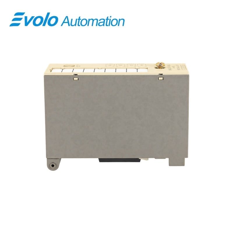
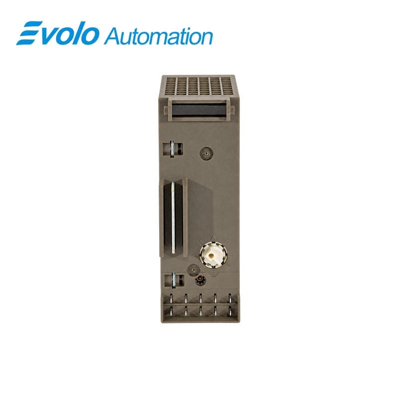
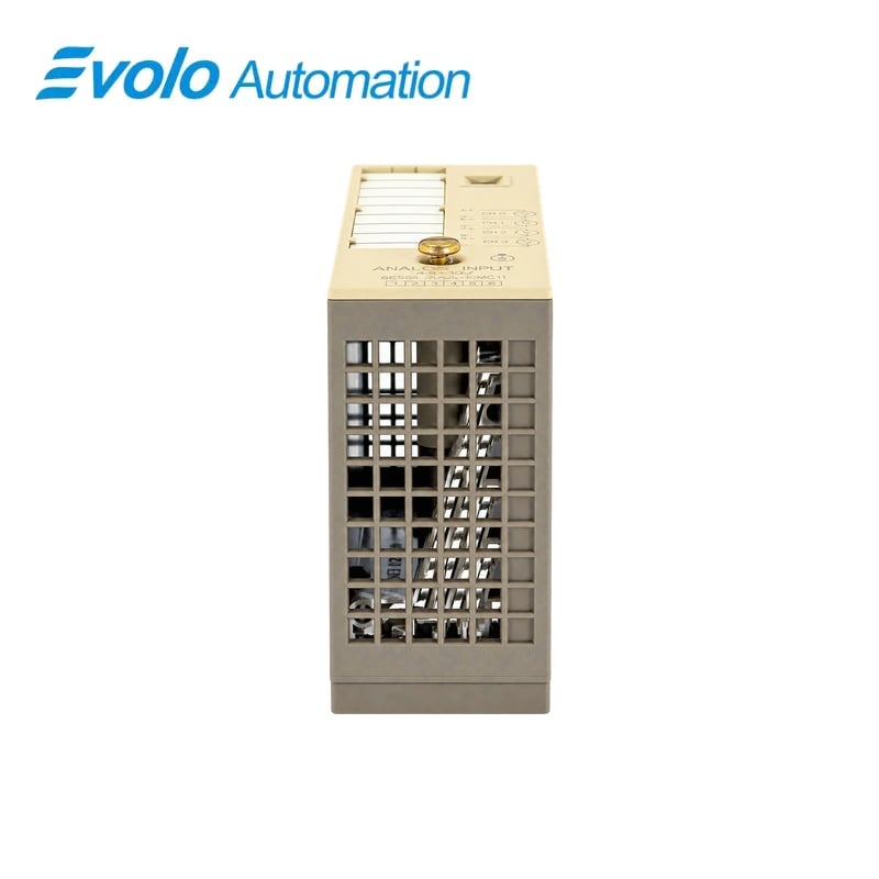
Siemens 6ES5464-8MC12 SIMATIC S5 Analog Input Module 4 x ±10 V
Manufacturer: Siemens
Condition: Brand New
Lead Time: In Stock
Origin: Germany
Warranty: 12 Months
Email: [email protected]
whatsApp: +86-18150117685
- Overview
- Hot Selling Models
- Recommended Products
Overview
- Use voltage signals within the nominal ±10 V measuring range.
- Wire the sensors using the two-wire input arrangement.
- Select one, two or four channels and the appropriate 50 Hz or 60 Hz integration timing.
- Keep the potential difference between inputs within ±1 V.
- Allow the typical 70 mA CPU supply current and use shielded wiring within the 200 m limit.
- Do not rely on a sensor wire-break diagnostic for this voltage-input module.
6ES5464-8MC12 SIMATIC S5 Analog Input Module 4 x ±10 V
An integrating voltage-input module with a ±10 V nominal range, selectable one-, two- or four-channel acquisition and signed digital representation.
At a Glance
| Brand | Siemens |
|---|---|
| Model | 6ES5464-8MC12 |
| Product Type | Bipolar voltage acquisition module |
| Core Function | Converting field voltages into signed process values |
| Application | Compatible SIMATIC S5-100U analog input assemblies |
Selectable acquisition
The module can operate with one, two or four input channels.
Bipolar process values
Nominal input values are represented by 2048 units with 12 bits plus sign.
CPU-powered electronics
The electronics draw a typical 70 mA from the CPU’s 9 V supply without an external L+ connection.
Product Overview
6ES5464-8MC12 acquires bipolar voltage signals for the compatible S5 analog input assembly.
Dual-slope conversion, selectable integration timing and signed process values support voltage measurement with the specified input loading and common-potential limits.
Key Functions
Acquire the selected voltage channels
One, two or four channels can be selected for signals within the nominal ±10 V range, using two-wire sensor connections.
Integrate the input signal
The dual-slope conversion uses 20 ms integration at 50 Hz or 16.6 ms at 60 Hz for the corresponding noise-suppression setting.
Deliver signed measured values
The output representation uses 12 bits plus sign in left-justified two’s-complement format, with 2048 units corresponding to the nominal range value.
Official Specifications
| Nominal Input Range | ±10 V |
|---|---|
| Selectable Channel Count | 1, 2 or 4 |
| Input Resistance | 50 kΩ |
| Sensor Connection | Two-wire connection |
| Galvanic Isolation | Inputs isolated from the grounding point, but not from one another |
| Digital Representation | 12 bits plus sign; left-justified two’s complement; 2048 units at nominal range value |
| Conversion Principle | Integrating voltage-time conversion, dual slope |
| Integration Time | 20 ms at 50 Hz; 16.6 ms at 60 Hz |
| Maximum Encoding Time per Input | At 2048 units: 60 ms at 50 Hz or 50 ms at 60 Hz; at 4095 units: 80 ms at 50 Hz or 66.6 ms at 60 Hz |
| Permissible Potential Difference | Between inputs: ±1 V maximum; inputs to central ground: 75 V DC or 60 V AC maximum |
| Noise Rejection | Common mode: at least 86 dB at 1 V peak-to-peak; series mode: at least 40 dB with interference below the rated input range, at integer multiples of 50/60 Hz ±1% |
| Basic Error Limit | ±0.2% |
| Operational Error Limit | ±0.45% over 0–60 °C |
| Linearity, Tolerance and Polarity-Reversal Errors | ±0.05% for each error component |
| Temperature Coefficients | Full-scale value: ±0.01%/K; zero point: ±0.002%/K |
| Maximum Shielded Cable Length | 200 m |
| Insulation Ratings | 9 V supply to ground: 12 V AC; inputs to 9 V supply: 60 V AC; both tested with 500 V AC |
| Electronics Supply | Typical 70 mA from the CPU’s 9 V supply; no external L+ supply |
| Typical Power Dissipation | 0.7 W |
| Approximate Weight | 230 g |
Frequently Asked Questions
Can 6ES5464-8MC12 measure negative voltage as well as positive voltage?
The nominal input range extends from −10 V to +10 V.
Must I connect all four signal channels when using 6ES5464-8MC12?
The acquisition configuration can select one, two or four channels.
How should I choose the integration timing for 6ES5464-8MC12 in a 60 Hz installation?
Use the 16.6 ms integration setting for 60 Hz rather than the 20 ms setting for 50 Hz.
Are the input channels on 6ES5464-8MC12 isolated from each other?
The inputs are isolated from the grounding point but are not galvanically isolated from one another.
Do I need a separate L+ supply for 6ES5464-8MC12?
The electronics use the CPU’s 9 V supply at a typical 70 mA and require no external L+ supply.
Will 6ES5464-8MC12 report a broken sensor wire directly?
The voltage-input module does not provide sensor wire-break indication.
How far can I run shielded sensor wiring to 6ES5464-8MC12?
The specified maximum shielded cable length is 200 m.