EN




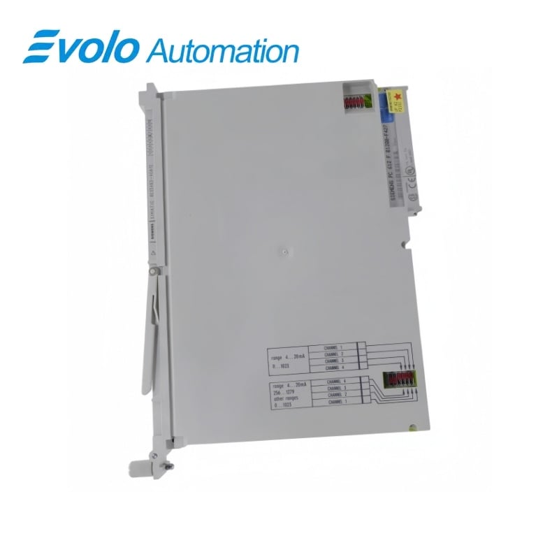
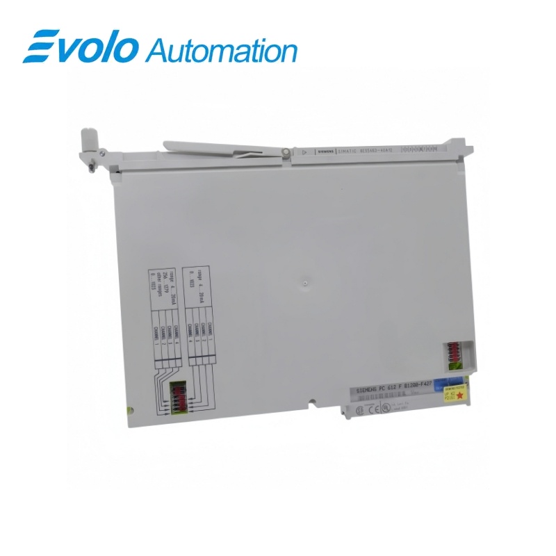
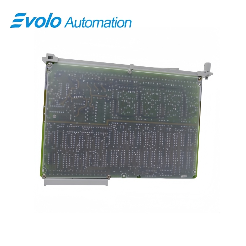
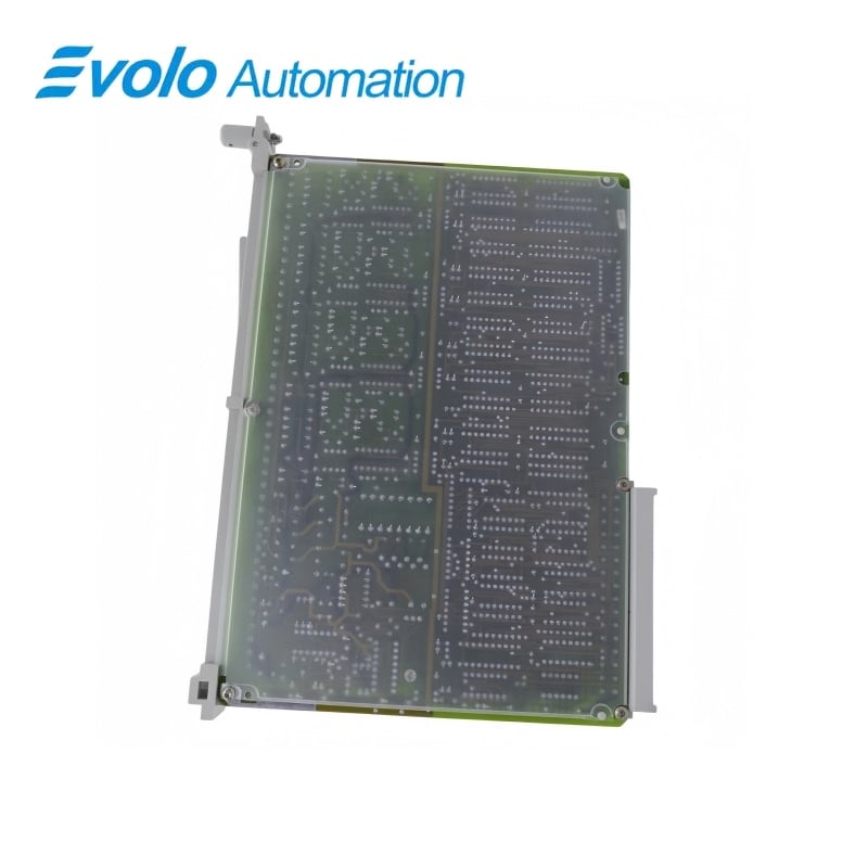
Siemens 6ES5463-4UA12 SIMATIC S5 463 Four-Channel Analog Input Module
Manufacturer: Siemens
Condition: Brand New
Lead Time: In Stock
Origin: Germany
Warranty: 12 Months
Email: [email protected]
whatsApp: +86-18150117685
- Overview
- Hot Selling Models
- Recommended Products
Overview
- Match the four-input 4UA12 variant and the intended S5 rack configuration.
- Preserve the selected voltage or current range and transmitter connection for every channel.
- Provide the bus supply, analog load supply and 24 V F+/F− enable.
- Account for the isolation change caused by two-wire transmitter commons connected to L−.
- Preserve the starting address and two-byte channel allocation.
- Use shielded measuring cables and observe the separate-routing condition for lengths up to 500 m.
6ES5463-4UA12 SIMATIC S5 463 Four-Channel Analog Input Module
A four-input S5 463 module with front-connector range selection, isolated measuring channels and 20 ms integration at 50 Hz.
At a Glance
| Brand | Siemens |
|---|---|
| Model | 6ES5463-4UA12 |
| Product Type | Voltage and current analog input module |
| Core Function | Converts process voltage and current measurements to digital values |
| Application | Compatible SIMATIC S5 U-series process input stations |
Four process inputs
Voltage, current and two- or four-wire transmitter connections can be combined as required.
Front-connector range selection
Select the required voltage or current range at the front connector.
50 Hz conversion timing
Integration, coding and the four-value acquisition cycle are each specified at 20 ms.
Product Overview
6ES5463-4UA12 acquires four voltage or current measurements for a compatible SIMATIC S5 U-series system.
The integrating voltage-to-frequency conversion stage provides 11-bit two’s-complement measured-value representation with 1024 units in the rated range; signal ranges are selected at the front connector, and the module requires separate bus, analog and enable supplies.
Key Functions
Mixed process-signal acquisition
Voltage sensors, current sensors and two- or four-wire transmitters can be connected in any combination using the available front-connector ranges.
Defined data representation
Measured values use two-byte channel addresses, with selectable 0–1023 or 256–1279 representation for each 4–20 mA input.
Isolated measurement integration
The standard measuring arrangement isolates the channels from each other and from the reference point, while two-wire transmitter wiring removes the isolation to the load supply when the input common is connected to L−.
Official Specifications
| Voltage input ranges | −0.05 to +1 V; −0.5 to +10 V |
|---|---|
| Current input ranges | −1 to +20 mA; 4–20 mA for two- or four-wire transmitters |
| Measured-value representation | 11-bit two’s complement; 1024 units in rated range |
| Conversion method | Integrating voltage-to-frequency conversion |
| Standard input isolation | Between the four inputs and reference point M, and between inputs |
| Permissible reference-potential difference | Maximum 25 V AC or 60 V DC between sensors and module, or between sensors |
| Digital-section supply | 5 V ±5% from system bus; typical 150 mA |
| Analog-section supply | 24 V load supply; approximately 150 mA |
| Module enable supply F+/F− | 24 V; approximately 7 mA |
| Integration, coding and four-value cycle time | 20 ms at 50 Hz for the 4UA12 variant |
| Input impedance, 1 V range | Greater than 10 MΩ |
| Input impedance, 10 V range | 90 kΩ |
| Input impedance, 20 mA range | 50 Ω |
| Input impedance, 4–20 mA range | 62.5 Ω |
| Overflow fault indication | Provided when overdrive reaches 50% or more |
| Maximum non-destructive input voltage | ±30 V; 75 V for up to 1 ms with duty factor 1:10 |
| Common-mode interference suppression | At least 80 dB from 0 to 50 kHz |
| Differential-mode interference suppression | At least 40 dB with interference amplitude ≤0.1 of the selected measurement range peak value |
| Isolation test | 500 V AC between inputs and ground point and between inputs |
| Shielded measurement cable length | Maximum 200 m; up to 500 m when routed separately from power cables |
Frequently Asked Questions
Can voltage and current transmitters be mixed on 6ES5463-4UA12?
Voltage sensors, current sensors and two- or four-wire transmitters may be connected in any combination using the appropriate input-range wiring.
What isolation change must be considered with two-wire transmitters on 6ES5463-4UA12?
Connecting the affected input common to L− for a two-wire transmitter removes the electrical isolation between those channels and the L+/L− supply.
Why might 6ES5463-4UA12 remain inaccessible even when its bus and analog supplies are present?
The bus interface is activated only when 24 V is applied to the F+ and F− enable terminals.
Which digital formats can I select for the 4–20 mA inputs of 6ES5463-4UA12?
Each channel can be switched individually between the 0–1023 and 256–1279 representations.
How is a channel address calculated for 6ES5463-4UA12?
The channel subaddress is the module starting address plus twice the channel number.
When can measurement cables for 6ES5463-4UA12 extend beyond 200 metres?
Shielded measurement cables may extend to 500 m when they are routed separately from power cables.
Which integration timing applies when replacing 6ES5463-4UA12?
The 4UA12 variant has a 20 ms integration time at 50 Hz.