EN
EN




- Overview
- Specifications
- Description
- Applications
- Safety Precautions
- Installation
- Operation
- Frequently Asked Questions
- Recommended Products
Overview
Place of Origin: |
USA |
Brand Name: |
GE |
Model Number: |
IS200VCRCH1BBC |
Packaging Details: |
Original new Factory Sealed |
Delivery Time: |
5-7 days |
Payment Terms: |
T/T |
Supply Ability: |
In stock |
Specifications
|
Part Number: |
IS200VCRCH1BBC |
|
Manufacturer: |
General Electric |
|
Country of Manufacture: |
United States of America (USA) |
|
Product Type: |
Discrete Input/Output Board |
|
Series: |
Mark VI |
|
Number of Inputs: |
48 discrete inputs across four terminal boards |
|
Number of Outputs: |
24 relay outputs |
|
Dimensions: |
2 x 18.6 x 26.1 cm |
|
Weight: |
0.32 kg |
|
Operating Temperature: |
-30 to 65 °C |
|
Max Response Time On: |
25 ms |
|
Max Response Time Off: |
25 ms |
|
Relay Contact Material: |
Silver cadmium-oxide |
|
LED Indicators: |
RUN – flashing green, FAIL – solid red, STATUS – steady orange for diagnostic alarm |
|
AC Supply: |
Grounded neutral, MOVs protect against 125 V DC + AC peak voltage |
|
MOV Rating: |
Withstands 120 V AC peak without failure |
Description
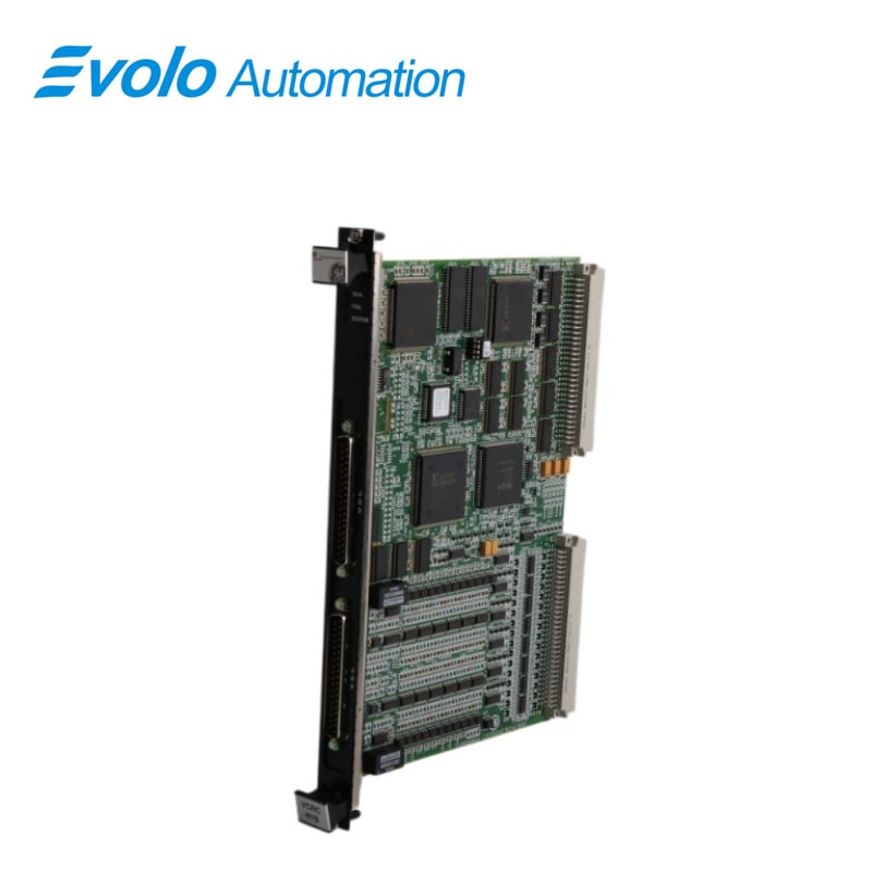
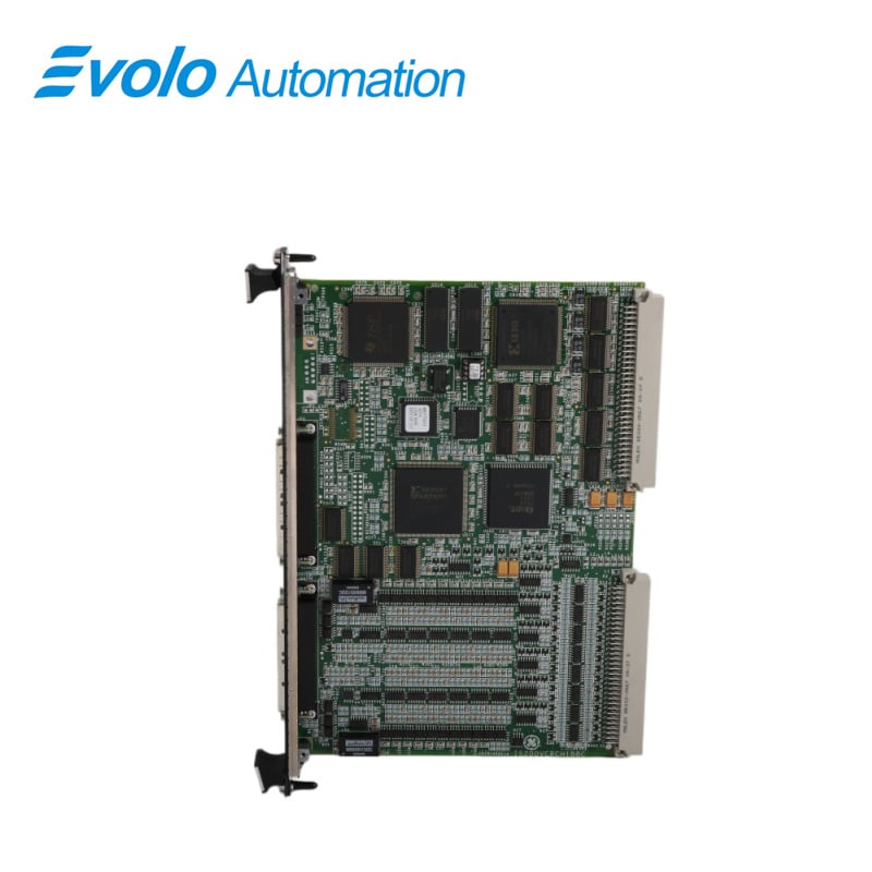
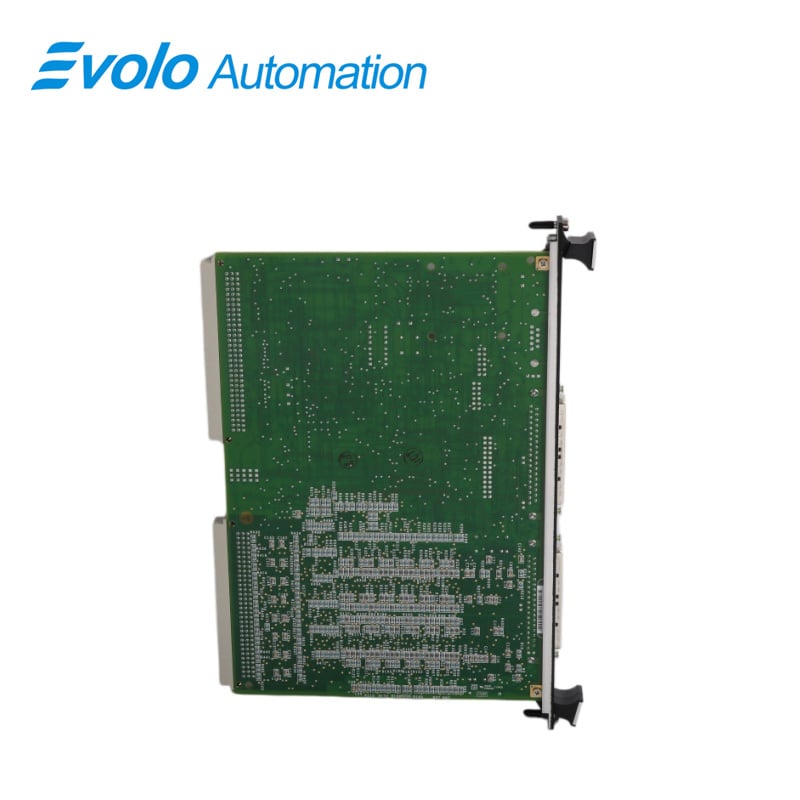
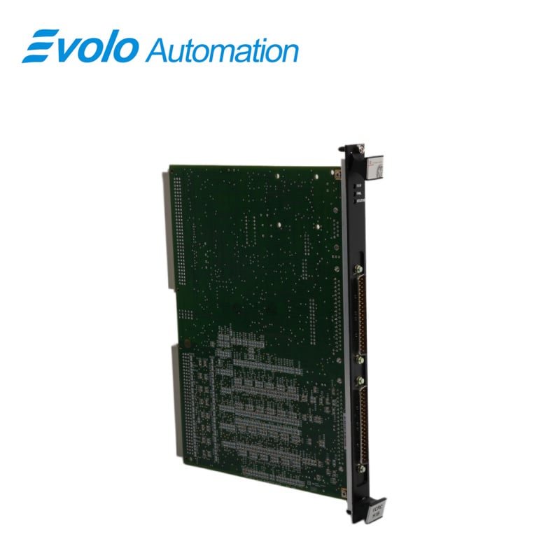
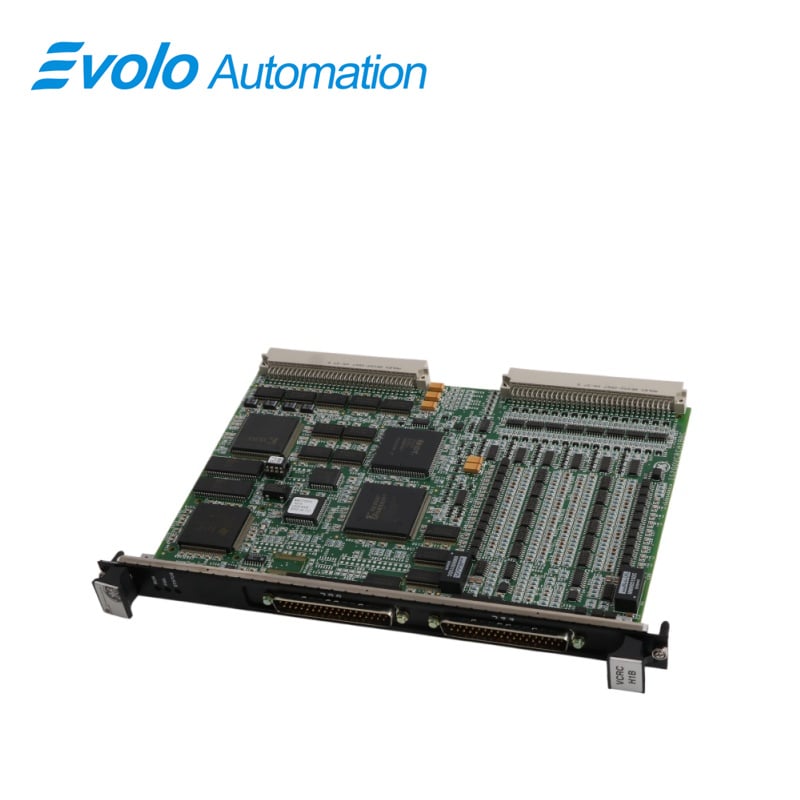
IS200VCRCH1BBC is a discrete input/output board developed by GE. It is a part of Mark VI control system. The Discrete Input/Output board, along with its associated daughterboard, facilitates the management of 48 discrete inputs and the control of 24 relay outputs, distributed across four terminal boards. This board is designed to fit into a narrower, single-slot configuration and is installed within the VME I/O rack. The rack is equipped with two sets of J3/J4 plugs to accommodate cables connecting to the TBCI (Contact Input with Group Isolation) and TRLY (Trip Relay) terminal boards.
Applications
Thermal power plants: GE Frame 6/7/9 series gas turbines and steam turbine units.
Oil and gas refineries: Large compressor units and self-contained power plants.
Nuclear power plants: Conventional island (non-safety level) auxiliary equipment control systems.
Combined cycle power plants (CCGT): Waste heat boiler and turbine linkage control.
Large petrochemical plants: Cracking units and high-reliability power centers.
Steel and metallurgical plants: High-power motor drive lines and power distribution logic control.
Large paper mills: Process protection for combined heat and power (CHP) units.
Safety Precautions
1.Exercise caution to prevent inadvertent cross-connections between AC and DC voltages.
2.Implement proper labeling and insulation measures to clearly differentiate between Ac and Dc circuits
3.Adhere to recommended wiring practices and safety guidelines to maintain system reliability and prevent electrical hazards.
Installation
1 Prepare for Installation: Ensure the VME I/O processor rack is powered down to prevent electrical hazards during installation.
2 Board Insertion: Carefully slide the DIO board into the designated slot within the VME I/O rack. Using your hands, push the top and bottom levers inward to securely seat the edge connectors of the board.
3 Secure the Board: Once the board is correctly positioned, tighten the captive screws located at the top and bottom of the front panel. This ensures the board remains securely fastened within the rack.
4 Power On and Verification: Restore power to the VME rack once the board is securely installed. Verify the status of the diagnostic lights located at the top of the front panel. These lights provide valuable information regarding the operational status of the board.
Operation
1 Operates by passing input voltages through optical isolators, ensuring electrical isolation for safety and reliability purposes. These input signals are sampled at specific frame rates to facilitate control functions effectively. Additionally, for sequence of events (SOE) reporting, the signals are sampled at a rate of 1 millisecond (ms) to capture events accurately and in real-time.
2 Once the signals are sampled, the board transfers them over the VME (Versa Module Eurocard) backplane to the VCMI. The VCMI acts as an intermediary, receiving the signals and forwarding them to the controller for further processing and decision-making.
3 This process ensures that input signals from various sources are efficiently handled, sampled at appropriate rates, and reliably transmitted to the controller via the VME backplane, enabling effective monitoring and control of voltage conditions within the system.
Frequently Asked Questions
Q: What is IS200VCRCH1BBC?
A: IS200VCRCH1BBC is a discrete input/output board developed by GE under the Mark VI series.
Q: What do the LEDs on the IS200VCRCH1BBC I/O board front panel indicate?
A: On IS200VCRCH1BBC, the normal RUN condition is indicated by a flashing green LED, while FAIL is represented by a solid red LED. The third LED, labeled STATUS, remains off under normal conditions but turns steady orange if a diagnostic alarm condition exists on the board.
Q: How does the diagnostic monitoring work on the IS200VCRCH1BBC I/O board?
A: The diagnostics on IS200VCRCH1BBC monitor each output by sampling and digitizing parameters such as voltage drops across current sense resistors, D/A outputs, and shutdown relay contacts. Standard diagnostics include high and low limit checks and configurable high and low system limit checks. If any output becomes unhealthy, a composite diagnostic alarm occurs.
Q: Can diagnostic signals on IS200VCRCH1BBC be individually managed?
A: Yes, diagnostic signals on IS200VCRCH1BBC can be individually latched and then reset with the RESET DIA signal once they return to a healthy state.
Q: What information does the ID device on each IS200VCRCH1BBC cable connector provide?
A: Each cable connector on IS200VCRCH1BBC has its own ID device containing the terminal board serial number, board type, revision number, and the JR, JS, and JT connector location. A mismatch detected by the I/O processor creates a hardware incompatibility fault.