EN
EN




- Overview
- Quick Detail
- Description
- Applications
- Feature
- FREQUENTLY ASKED QUESTIONS
- Recommended Products
Overview
Place of Origin: |
USA |
Brand Name: |
GE |
Model Number: |
DS215TCCAG1BZZ01 |
Packaging Details: |
Original new Factory Sealed |
Delivery Time: |
5-7 days |
Payment Terms: |
T/T |
Supply Ability: |
In stock |
Quick Detail
|
Part Number: |
DS215TCCAG1BZZ01 |
|
Manufacturer: |
General Electric |
|
Series: |
Mark V |
|
Product Type: |
Common Analog I/O Board |
|
Input Channels: |
8 Analog Inputs |
|
Input Resolution: |
12-bit / 16-bit |
|
Output Type: |
Voltage (0-10V, ±10V) |
|
Output Resolution: |
12-bit / 16-bit |
|
Input Type: |
Voltage (0-10V, ±10V) |
|
Communication Protocol: |
RS-485 |
|
Power Supply: |
24V DC ±10%, <5W |
|
Isolation: |
1500V |
|
Mounting Options: |
DIN Rail |
|
Operating Temperature: |
-20°C to 70°C |
|
Country/Region of Manufacture: |
United States |
Description
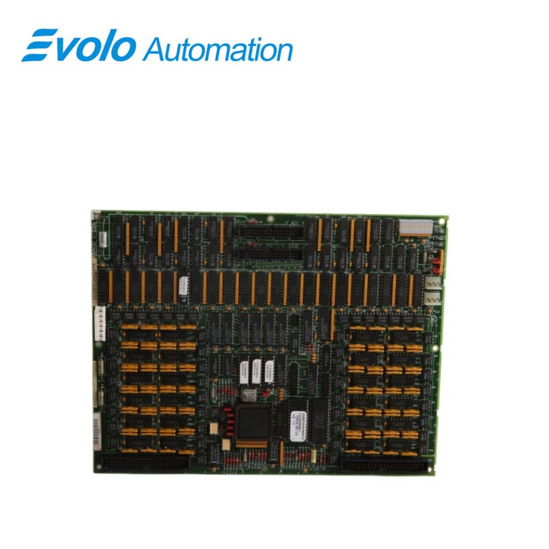
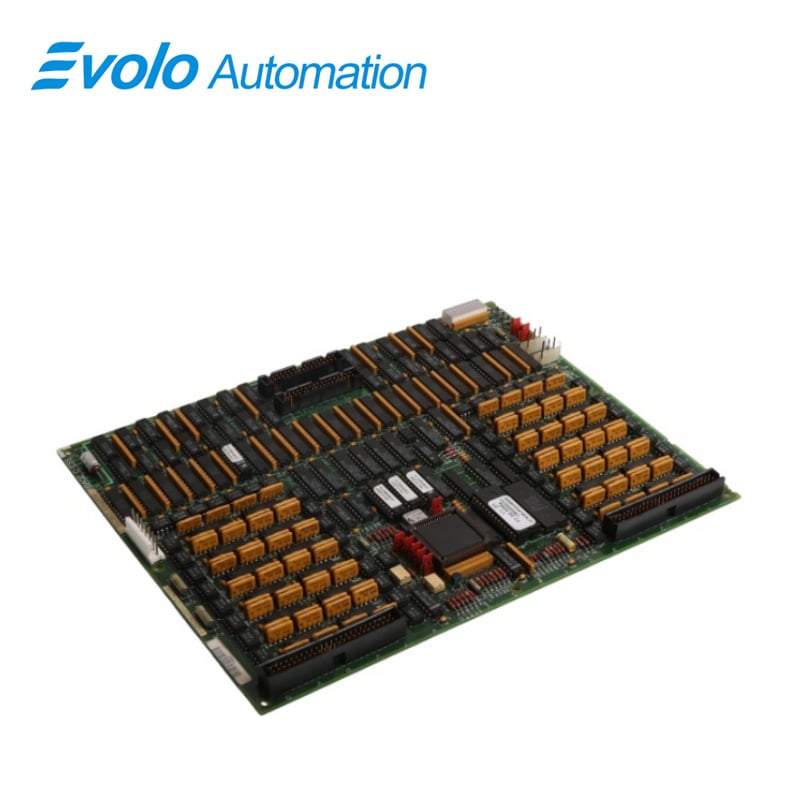
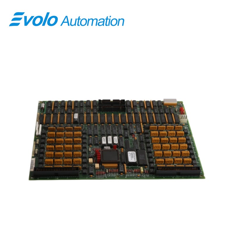
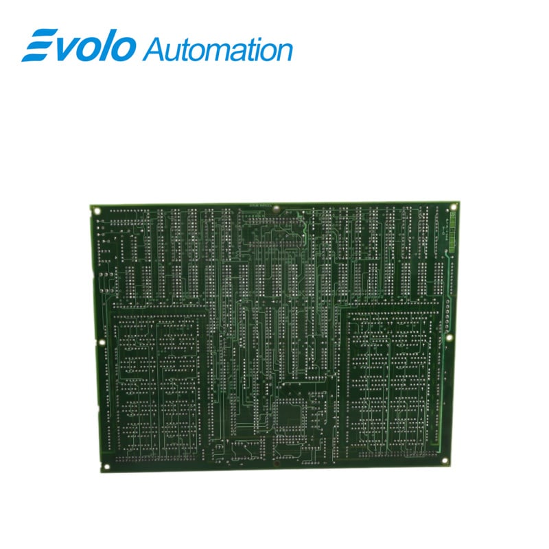
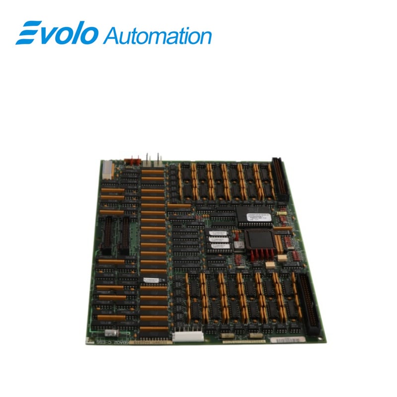
DS215TCCAG1BZZ01 is a Common Analog I/O Board manufactured and Designed by General Electric as part of the Mark V Series used in gas turbine control systems. The Common Analog I/O Board (TCcA) in the core processes and conditions analog signals from the CTBA, TBOA, and TBCA terminal boards. These signals include 4-20 mA inputs and outputs, RTD and thermocouple inputs, as well as shaft voltage and current inputs. The processed signals are transmitted to the STCA board via the 3PL connector.
Applications
Power plants: As part of the GE Mark V control system, it coordinates and monitors the start-up, load control, and protective tripping of heavy-duty gas turbines.
Oil and gas facilities: In large compressor stations or offshore drilling platforms, it is responsible for the critical logic control and signal interfaces of the power turbines.
Heavy industrial manufacturing: Used in self-contained power plant systems requiring large-scale, continuous power support, such as steel mills or aluminum plants.
Feature
TCCA CONNECTORS:
2PL: Distributes power from the TCPS board in the core.
3PL: Serves as the data bus between the TCCA, STCA, and TCCB boards in core 5, carrying conditioned signals for transfer to the COREBUS.
JAA: Transmits 4-20 mA output signals to the CTBA terminal board.
JBB: Carries shaft voltage, current signals, and 4-20 mA input signals from the CTBA terminal board.
Jcc/JDD: Carry RTD input signals from the TBCA terminal board.
JAR/S/T: Transmit thermocouple and cold junction input signals from the TBOA terminal board,
JC: Carries power supply diagnostic signals from TCPS.
TCCA CONFIGURATION:
Hardware: There are three hardware jumpers - J1, JP2, and JP3 on the TCCA board. J1 is used to enable/disable the serial RS232 port. JP2 is used to disable the oscillator for the card test. JP3 is used for factory tests.
Software: I/O configuration constants for the thermocouples, RTDs, mA inputs and outputs, and the shaft voltage and current settings are entered in the I/C Configuration Editor located on the HMl as described below.
TCCA 4-20 mA INPUT CIRCUIT:
The TCCA board processes 4-20 mA input signals from the CTBA terminal board via the JBB connector. The transducer current is dropped across a burden resistor, and the resulting voltage drop is read by the TCCA board and transmitted to the I/O Engine through the 3PL connector.
TCCA4-20 mAINPUT CIRCUIT:
The TCCA board provides the circuitry for driving 4-20 mA outputs to the CTBA terminal board via the JAA connector. These signals are typically used to drive remote instrumentation for monitoring
SHAFT MONITORING:
The TCCA board monitors voltage and current for the turbine shaft, receiving signals from the CTBA terminal board via the JBB connector and transmitting them to the I/O Engine through the 3PL connector. Located in R5 core location 2, the TCCA board, also known as the Turbine Control Micro Application Board A, is configured to handle:
RTD and thermocouple inputs
Milliamp inputs
Shaft voltage and current monitoring
FREQUENTLY ASKED QUESTIONS
Q: What is the function of the DS215TCCAG1BZZ01 TCCA board?
A: The TCCA (Common Analog I/O) board conditions and processes analog signals from various terminal boards in the core, including 4–20 mA inputs/outputs, RTD inputs, thermocouple inputs, shaft voltage inputs, and shaft current inputs.
Q: How does the DS215TCCAG1BZZ01 TCCA board process 4–20 mA signals?
A: 4–20 mA signals are received from the CTBA terminal board via the JBB connector. The transducer current is dropped across a burden resistor, and the resulting voltage is read by the TCCA board and sent to the I/O Engine through the 3PL connector.
Q: What is the function of the 3PL connector of DS215TCCAG1BZZ01?
A: The 3PL connector serves as the data bus between the TCCA, STCA, and TCCB boards in the R5 core. It transmits conditioned signals from the TCCA to the COREBUS, ensuring seamless communication and data exchange within the turbine control system.