EN
EN




- Overview
- Specifications
- Description
- Applications
- TCDA CONNECTORS
- FAQ
- Recommended Products
Overview
Place of Origin: |
USA |
Brand Name: |
GE |
Model Number: |
DS200TCDAH1BGD |
Packaging Details: |
Original new Factory Sealed |
Delivery Time: |
5-7 days |
Payment Terms: |
T/T |
Supply Ability: |
In stock |
Specifications
|
Manufacturer: |
General Electric |
|
Part Number: |
DS200TCDAH1BGD |
|
Product Type: |
Digital I/O Board |
|
Series: |
Mark V Speedtronic |
|
Dimensions: |
28 x 21.3 x 2 cm |
|
Weight: |
0.38 kg |
|
Voltage Range: |
24 VDC |
|
Current Range: |
4-20 mA |
|
Temperature Range: |
-40°C to 85°C |
|
Communication Interface: |
Modbus RTU |
|
Connectors: |
2 x 50-pin (JQ, JR), 2 x 3-pin / 9-pin (JX1, JX2) |
|
Configuration: |
8 jumpers (JP1-JP8) and PROM firmware module for hardware ID and network setup |
|
Input Channels: |
8 |
|
Output Channels: |
4 |
|
High-Speed Data Acquisition: |
Yes |
|
Built-in Diagnostics: |
Yes |
Description
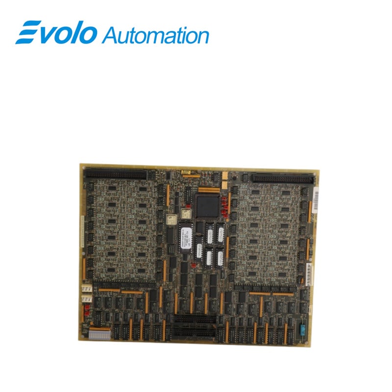
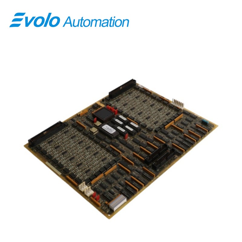
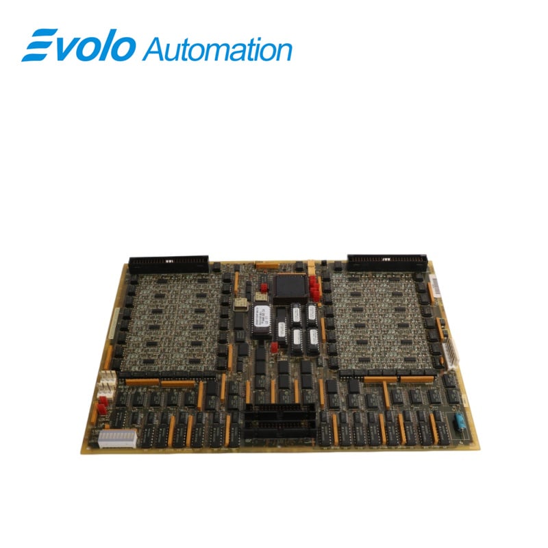
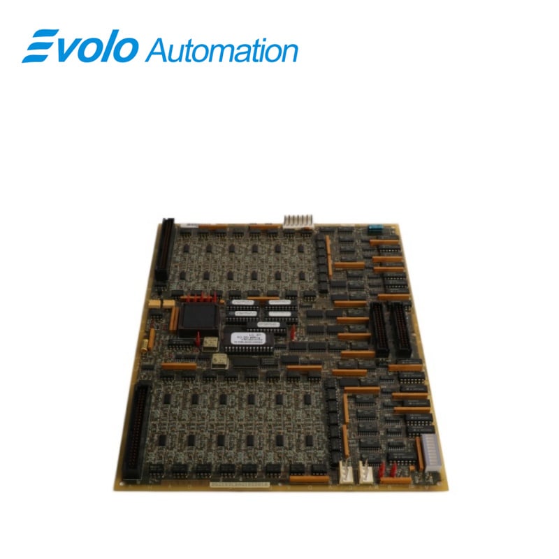
DS200TCDAH1BGD is a Digital I/O Board manufactured and designed by General Electric as part of the Mark V LM Series used in GE Speedtronic ControI Systems. The Digital I/O Board (TCDA) resides within the digital I/O cores, and, if applicable. It processes digital contact input signals from the DTBA and DTBB terminal boards and contact output signals (relay/solenoid) from the TCRA boards. These signals are transmitted via the IONET to the TCQC board in and, or to the CTBA terminal board in when is present. The TcDA board features eight hardware jumpers for various configurations, including IONET termination resistors, network ID settings, and enabling stall timer, while J1 and J8 are reserved for factory testing. Designed for reliable performance in demanding environments, it plays a critical role in turbine control by managing start-up, shutdown, and operational safety. Configuration and maintenance details are accessible through system documentation, including Appendix A and the operator interface.
Applications
Heavy-duty gas turbine control: Widely used in GE's entire range of gas turbines (such as the Frame 6/7/9 series), monitoring limit switches, circuit breaker status, and alarm contacts.
Steam turbine control: Responsible for valve control and logic protection interlocks in the power plant steam cycle.
Oil/petrochemical drive: Used in large electrical control cabinets in compressor stations, managing critical safety shutdown logic.
TCDA CONNECTORS
JP: Distributes power from the TCPS board in the R1,R2, and R5 cores to the Q11, Q21, and Q51 cores, respectively.
JQ: Connects to the JQR socket on the DTBA board, transmitting contact input signals from the DTBA board to the TCDA board.
JR: Connects to the JRR socket on the DTBB board, conveying contact input signals from the DTBB board to the TCDA board.
Jo1: Transmits contact output (relay/solenoid) signals to the TcRA board in location four. It is not utilized in Q11, as the relays in location 4 are directly controlled by TCQE in R1.
J02: Transmits contact output (relay/solenoid) signals to the TCRA board in location five
JX1: This is a shielded twisted pair cable for IONET signals.The TCDA board in the QD1 core sends signals to the JX2 connection on the TCEA board in location five of the C core.
JX2: Used for the same function as JX1. Either JX1 or JX2 can be employed for this purpose.
FAQ
Q: How is the IONET ID assigned to the DS200TCDAH1BGD?
A: The IONET ID of the DS200TCDAH1BGD is configured באמצעות hardware jumpers J4, J5, and J6. Different jumper combinations correspond to specific identification numbers, allowing the board to be uniquely recognized and communicate correctly within the system network.
Q: What is the purpose of the stall timer enabled by J7 of DS200TCDAH1BGD?
A: The stall timer, activated by jumper J7, is designed to monitor system activity. If the system becomes unresponsive or enters an abnormal state, the timer triggers protective actions, helping to prevent damage and maintain safe operation.
Q: How are input signals validated by the DS200TCDAH1BGD?
A: The DS200TCDAH1BGD validates input signals through built-in diagnostic circuits. These diagnostics check for signal integrity, consistency, and proper voltage levels before transmitting the data to other system components, ensuring reliable and accurate operation.