EN
EN




- Overview
- Specifications
- Description
- Applications
- Features
- Troubleshooting and Maintenance Recommendations
- FAQ
- Recommended Products
Overview
Place of Origin: |
USA |
Brand Name: |
GE |
Model Number: |
531X133PRUAMG1 |
Packaging Details: |
Original new Factory Sealed |
Delivery Time: |
5-7 days |
Payment Terms: |
T/T |
Supply Ability: |
In stock |
Specifications
|
Part Number |
531X133PRUAMG1 |
|
Product Type |
Process Interface Board |
|
Dimensions |
14.1×13.8×2 cm |
|
Weight |
0.14 kg |
|
Terminal Strip |
3-position terminal block (TACH+, TACH-) |
|
Connectors |
1×16-pin vertical header; 2× vertical pin cable connectors |
|
Test Points |
Multiple TP test sites |
|
Jumpers |
15 jumper switches |
|
Switches |
7-toggle single switch component |
|
Tachometer Inputs |
TACH+ / TACH- |
|
Terminal Type |
Screw terminal |
|
Mounting |
Factory drill hole at each corner |
Description
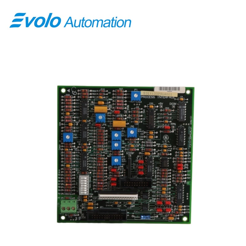
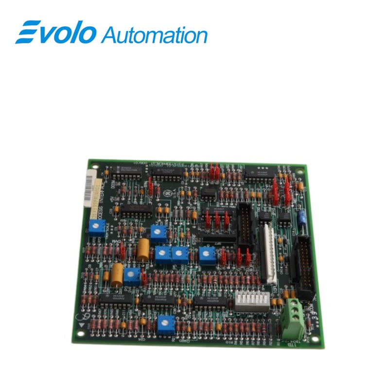
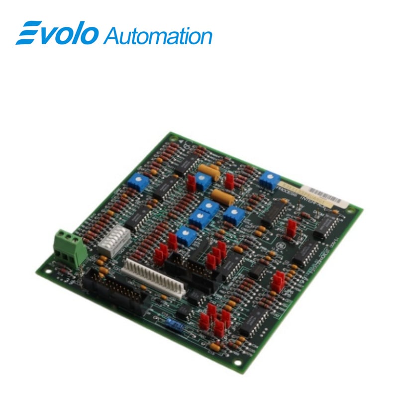
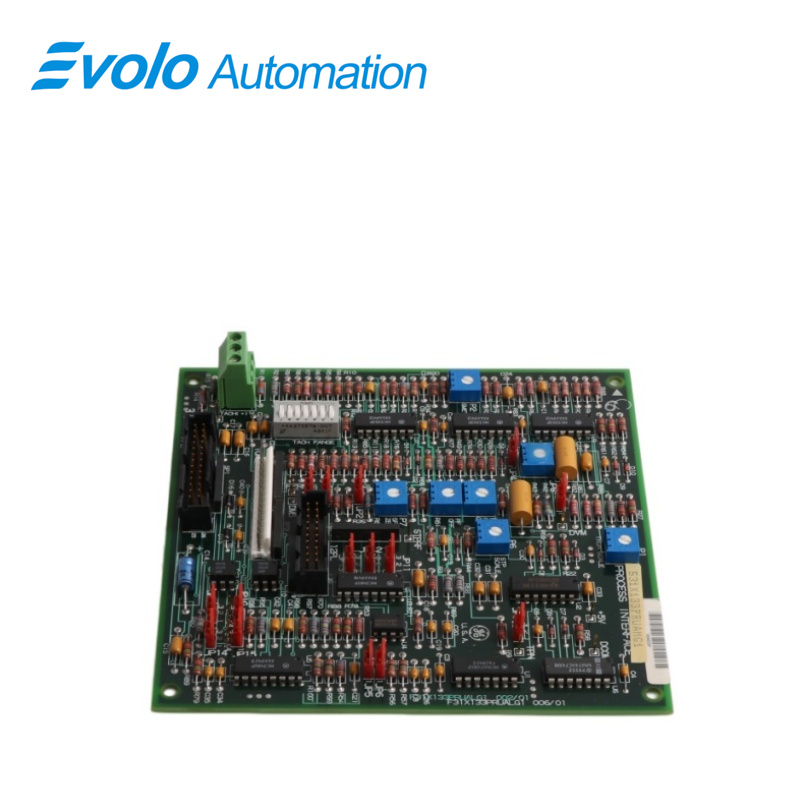
531X133PRUAMG1 is a GE Process Interface Board developed by General Electric. Several general-purpose drive systems from GE are compatible with this PCB's design. It converts and manages analog and digital input signals to ensure reliable communication with connected control hardware.
Applications
Precision strip mill: Used for closed-loop speed control of rolling drives via TACH feedback to stabilize line speed.
Chemical fiber and textile mill: Applied in winding machine control, using 15 jumpers to adjust feedback gain for different yarn types.
Heavy machinery mill: Serves as an interface in CNC auxiliary drives, using a 7-bit DIP switch for mode selection.
Paper machinery mill: Enables multi-section synchronization monitoring, with test points supporting real-time signal checks.
Rubber processing plant: Used in mixer drives, with rugged pin connections and mounting holes for vibration resistance.
Features
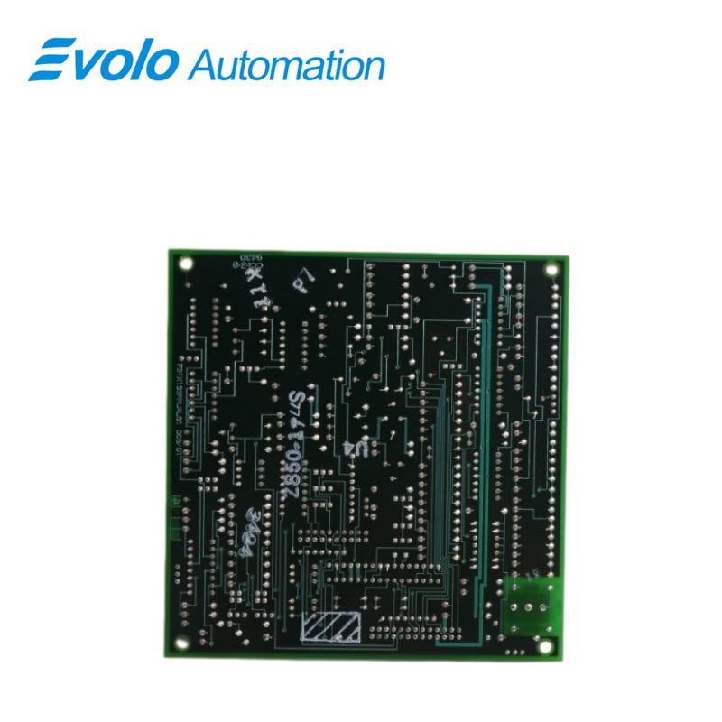
This board has been drilled in each corner and engraved with codes such as 002/0, 94V-0, FR00/0, and the secondary board number.
The Board contains two vertical pin male cable connectors, a header connector, and a terminal strip with three screw locations. Individual terminal pins on the board are labeled with things like "+5V" and "DcOM." These components enable the board to communicate with and connect to other boards or off-board components.
Troubleshooting and Maintenance Recommendations
Troubleshooting: If the system reports "speed signal lost," the first step should be to measure the input voltage of the TACH+/- terminals. Use the onboard TP test points to compare the actual signal with the feedback value to confirm whether the 15 jumper settings have been erroneously adjusted.
Maintenance Recommendations: It is recommended to regularly tighten the screws on the TACH terminals to prevent vibration from increasing contact resistance. For 7-position DIP switches, a configuration file should be created to avoid inconsistencies in settings when replacing spare parts.
FAQ
Q: How do I connect an external tachometer signal to the 531X133PRUAMG1?
A: Users connect signal wires to TACH+ and TACH– via the 3-position terminal block.
Q: What are the 15 jumpers on the 531X133PRUAMG1 primarily used for?
A: They set feedback range, filter frequency, and internal logic paths.
Q: How many external cable connections does the 531X133PRUAMG1 support?
A: It has one 16-pin header and two vertical cable connectors for multiple harness connections.
Q: How can I perform performance testing without disassembling the 531X133PRUAMG1?
A: TP test points allow real-time signal measurement using an oscilloscope or multimeter.
Q: What is the purpose of the 7-bit DIP switch on the 531X133PRUAMG1?
A: It defines operating logic and system addressing for field configuration.