EN
EN




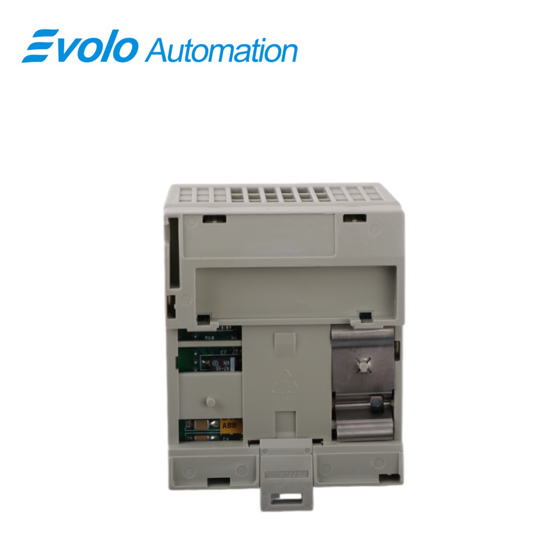
- Overview
- Specifications
- Description
- Applications
- Front Panel
- Maintenance Recommendations
- FAQ
- Recommended Products
Overview
Place of Origin: |
Sweden |
Brand Name: |
ABB |
Model Number: |
200-APB12 200APB12 |
Packaging Details: |
Original new Factory Sealed |
Delivery Time: |
5-7 days |
Payment Terms: |
T/T |
Supply Ability: |
In stock |
Specifications
|
Parameter |
Value |
|
Product Name |
200-APB12 200APB12 |
|
Dimensions |
20 x 11.3 x 12.6 cm (or W68 x H88 x D69 mm) |
|
Weight (Net) |
0.18 kg |
|
Input Voltage |
+24 V DC nominal (19.2–31.2 V DC) |
|
Power Consumption |
400 mA max (from external 24 V DC supply) |
|
Power Dissipation |
7.68 W max at 19.2 V DC |
|
I/O Capacity |
8 I/O units |
|
Communication Protocol |
PROFIBUS DP |
|
Communication Speed |
Up to 12 Mbit/s |
|
Status Indicators |
2 red/green LEDs (unit status & communication status) |
|
Operating Temperature |
0 °C to +55 °C |
|
Storage Temperature |
-40 °C to +85 °C |
|
Humidity |
5–95% (non-condensing) |
|
Certifications |
CE marked, EMC Directive 89/336/EEC (EN 50081-2, EN 50082-2) |
|
Agency Approval |
PNO (PROFIBUS Nutzerorganisation) |
|
WEEE Category |
5 (Small Equipment, <50 cm) |
|
Number of Batteries |
0 |
Description
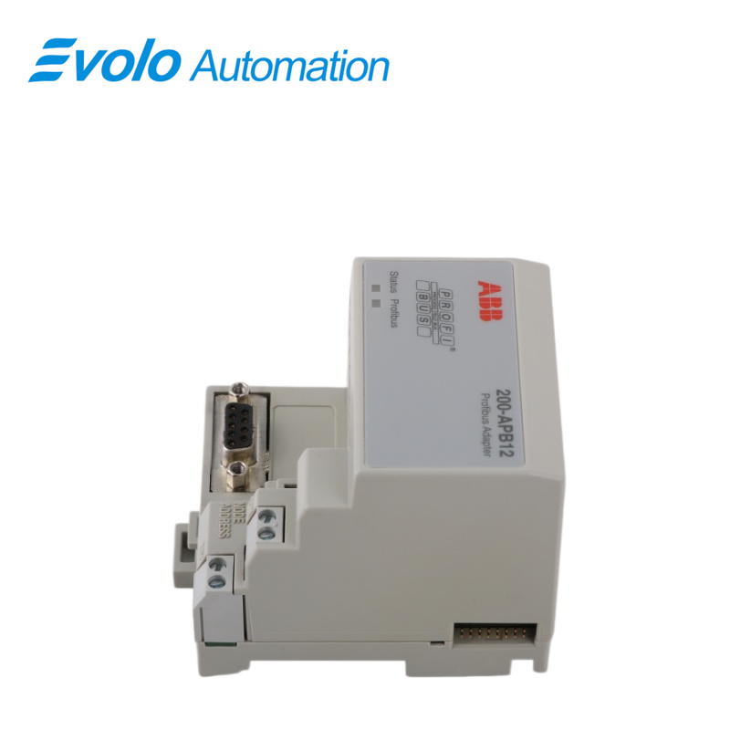
The 200-APB12 200APB12 adapter acts as a slave device to a DP master controller on the PROFIBUS network and transfers data between the controller and the I/O units. For information on PROFIBUS-DP installation, see “Installation Guidelines for PROFIBUS-DP/FMS” (available from ABB Automation Products. The power is taken from a 24 V DC supply. The status of the adapter is indicated by the LEDs on the front panel. The unit also supports I/O units with internal current via the serial I/O bus.
Applications
Automobile assembly plants: On large painting or final assembly lines, sensor signals from each workstation are transmitted back to the main PLC via PROFIBUS.
Wastewater treatment plants: Pump stations and level monitoring points distributed throughout the plant are connected to the central control network through this module.
Paper mills/chemical fiber plants: On long-distance production lines, this module is used to collect dispersed temperature, pressure, and limit signals.
Food packaging plants: Integrated into the control cabinet of multi-head scales or packaging machinery, enabling modular I/O expansion.
Front Panel
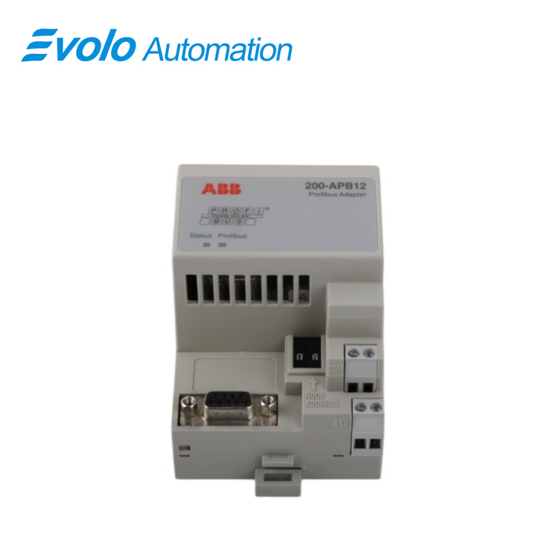
1 Red/Green LED, adapter status indicator
2 Red/Green LED, PROFIBUS communication link indicator
3 PROFIBUS-DP network 9-pin D-type female connector
4 Node address indicator
5 +24 V DC connection terminals
6 0 V DC connection terminals
7 Serial I/O bus connector
8 Push-button switches for node address setting
Maintenance Recommendations
Prevent Vibration: The S200 module is pluggable. In factories with high vibration levels, ensure the guide rail clips are securely fastened.
GSD Backup: Factory technicians should retain the module's GSD configuration file for quick remapping when replacing hardware with different versions.
FAQ
Q: Does the 200-APB12 200APB12 adapter support PROFIBUS DP-V1?
A: The 200-APB12 200APB12 primarily supports standard PROFIBUS DP-V0 communication for cyclic data exchange, which is sufficient for most industrial I/O read/write applications.
Q: What is the maximum communication distance of the 200-APB12 200APB12?
A: For the 200-APB12 200APB12, the maximum communication distance depends on the baud rate. It can reach up to 1000 meters at 187.5 kbps, while at 12 Mbps it is recommended not to exceed 100 meters, using a dedicated purple-shielded PROFIBUS cable.
Q: Do I need to reprogram after replacing the 200-APB12 200APB12 module?
A: If the hardware address (DIP switch settings) of the 200-APB12 200APB12 matches the original device and the GSD file version is compatible, replacement is typically “plug-and-play” without requiring PLC logic modification.
Q: Does the 200-APB12 200APB12 adapter include a terminating resistor?
A: The 200-APB12 200APB12 itself does not include an internal terminating resistor. If it is the last node on the PROFIBUS line, the terminating resistor must be manually set to “ON” on the PROFIBUS connector.
Q: Why does the system display “I/O Error” on the 200-APB12 200APB12?
A: For the 200-APB12 200APB12, this error may occur if the total number of connected I/O modules exceeds 8, or if one or more modules are not receiving sufficient power from the system.