EN
EN




- Overview
- Specifications
- Description
- Applications
- Feature
- REPAIR/REPLACEMENT
- FAQ
- Recommended Products
Overview
Place of Origin: |
Sweden |
Brand Name: |
ABB |
Model Number: |
IMDSI14 |
Packaging Details: |
Original new Factory Sealed |
Delivery Time: |
5-7 days |
Payment Terms: |
T/T |
Supply Ability: |
In stock |
Specifications
|
Parameter |
Value |
|
Model |
IMDSI14 |
|
Description |
Digital Input Module, Bailey Infi 90 |
|
Dimension |
3.5x31x17.6 cm |
|
Weight |
0.2 kg |
|
Input Points |
16 points |
|
Input Voltage |
48 VDC |
|
Input Current |
4.7 mA |
|
Turn-on Voltage (Min) |
20.1 VDC |
|
Turn-off Voltage (Max) |
29 VDC |
|
DC Response Time (Debounce Filter) |
17 ms (fixed) |
|
Operating Temperature |
0° to 70°C (32° to 158°F) |
|
Relative Humidity |
5% to 95% up to 55°C; 5% to 45% at 70°C (non-condensing) |
|
Pollution Degree |
1 (no condensation) |
|
Atmospheric Pressure |
Sea level to 3 km (1.86 miles) |
|
Air Quality |
Noncorrosive (per ISA S71.04, Class LA, LB, LC - level 1) |
|
Electrostatic Discharge (IEC 1000-4-2, EN 61000-4-2) |
Contact: ±6 kV; Air: ±8 kV |
|
Electromagnetic Immunity |
Unmodulated rms: 10 V/m; Amplitude modulated 80% AM (1 kHz); Source impedance: 150 Ω |
Description
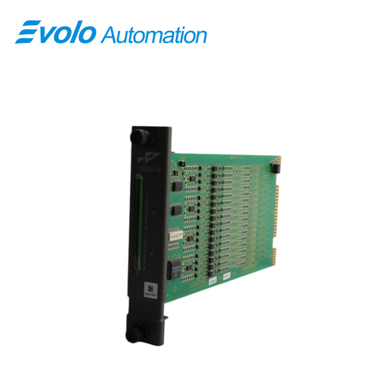
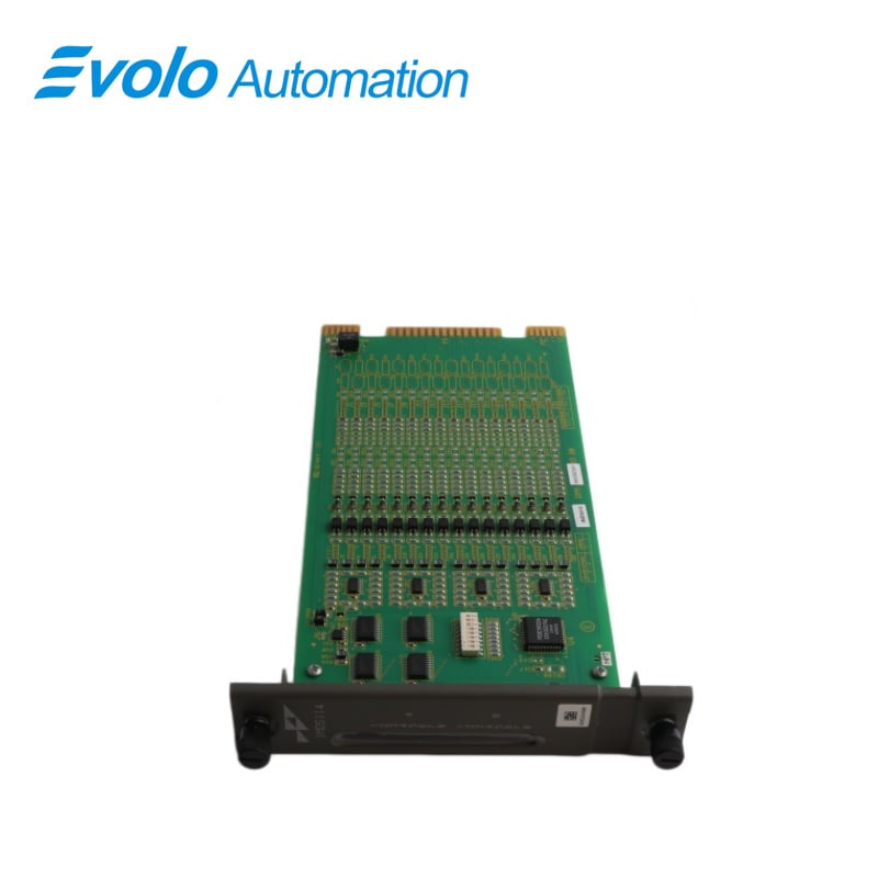
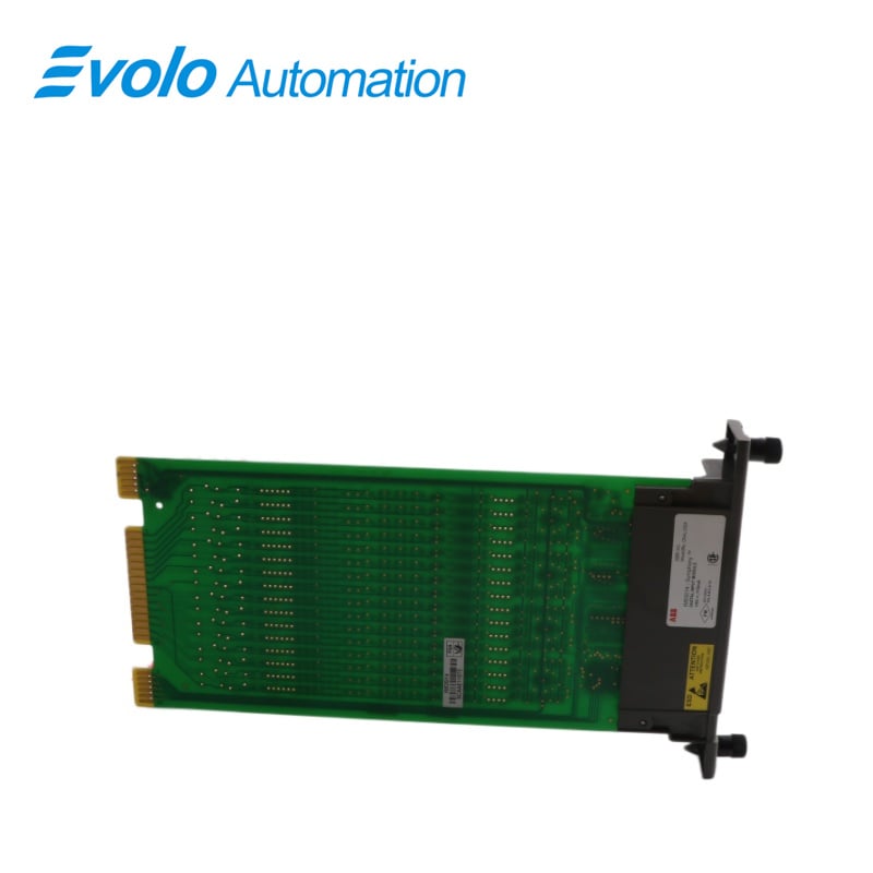
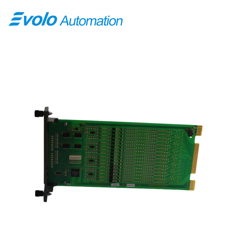
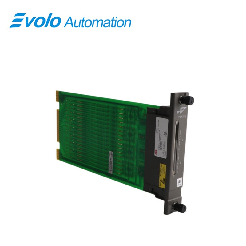
The IMDSI14 digital input module consists of a single printed circuit board that occupies one slot in a module mounting unit (MMU). It monitors two separate groups of eight digital inputs. Twelve inputs are isolated from each other; the remaining two pairs share common positive input lines. Two captive screws on the module faceplate secure it to the MMU. Sixteen front panel LED status indicators (group A and group B) display the input status and provide aid in system test and diagnosis. The digital input module has three card edge connectors for external signals and power (P1, P2 and P3). P1 connects to common (ground) and +5 VDC power. P2 connects the module to the I/O expander bus to communicate with a control module. P3 inputs the digital signals using a cable connected to a termination unit (TU) or termination module (TM). The terminal blocks (physical connection points) for field wiring are on the TU/TM.
Applications
Industrial automation: used for the control and monitoring of production lines, robots, sensors, and actuators.
Process control: Used in industries such as chemical, pharmaceutical, food and beverage.
Safety systems: used for mechanical guards, safety doors, and emergency stop systems.
Other industrial equipment: such as papermaking machinery, cement production lines, mining equipment, etc.
Feature
High reliability: The module is manufactured with high-quality components and can operate stably in harsh industrial environments.
Multifunctionality: Supports multiple signal types (such as TTL, sink and source) and has overcurrent, overvoltage and undervoltage protection functions.
Easy to integrate: The modular design is compact and supports DIN rail mounting, making it easy to integrate with existing systems.
Fast response: The typical response time is 10ms, ensuring real-time data transmission.
REPAIR/REPLACEMENT
If you determine the DSI is faulty, replace it with a new one.
DO NOT try to repair the module; replacing components may affect the module performance. You can remove the module while system power is supplied. To replace a module:
1. Push and turn the two front panel captive retaining screws one half turn to unlatch the module. It is unlatched when the slots on the screws are vertical and the open end of the slots face away from the module.
2. Gently slide the module out of the MMU.
3. Configure the replacement module switch and jumper settings. Refer to Address Selection Switch (S1) and Digital Input Jumper Settings in Section 3. Make certain these adjustments are set the same as the original module.
4. In the same slot assignment as the original module, align the replacement module with the guide rails in the MMU; gently slide it in until the front panel is flush with the top and bottom of the MMU frame and the module is fully seated in the cable to the termination device.
5. Push and turn the two captive retaining screws on the module faceplate one half turn to the latched position. It is latched when the slots on the screws are vertical and the open ends face the center of the module.
6. Return to normal operation.
FAQ
Q: What is the IMDSI14?
A: It is a Bailey Infi 90 Digital Input Module.
Q: What about your delivery time of IMDSI14?
A: Generally 1-3 days after receiving your payment. The specific delivery time depends on the type and quantity of the order.
Q: How long is the warranty period of IMDSI14?
A: We offer a standard one-year warranty for all new and original products.
Q: Do you offer any discounts?
A: Yes! For discounts on IMDSI14, please contact John for the best offer.