EN
EN




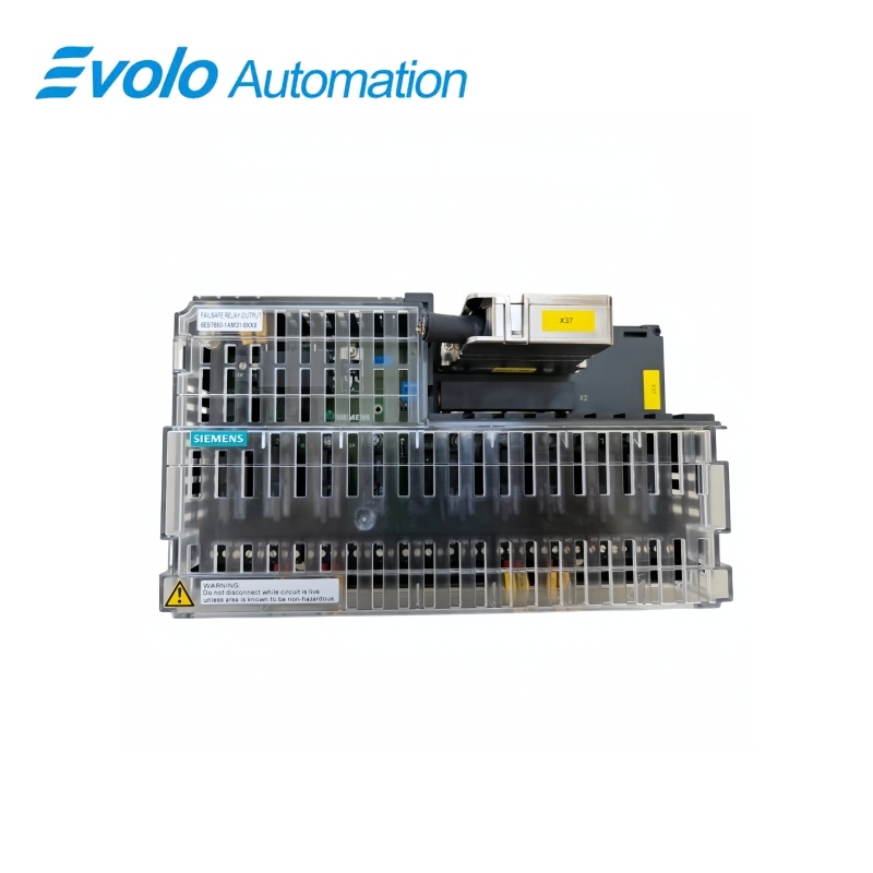
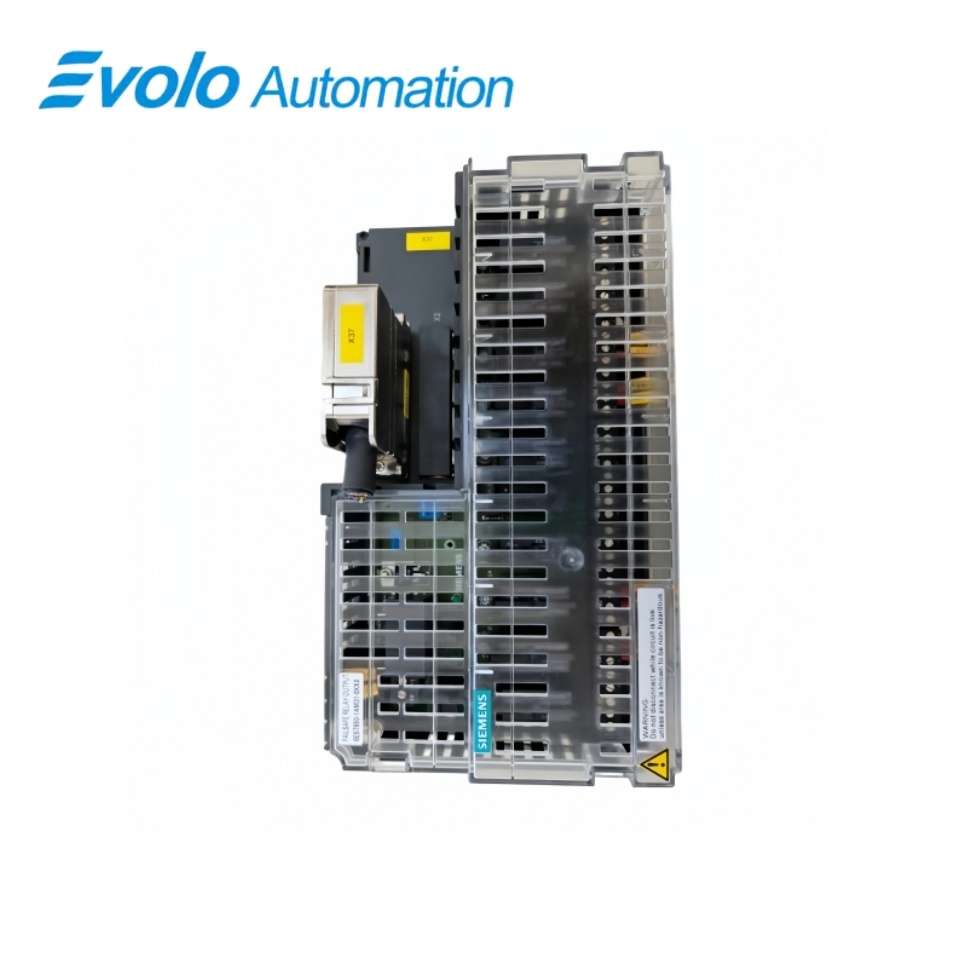
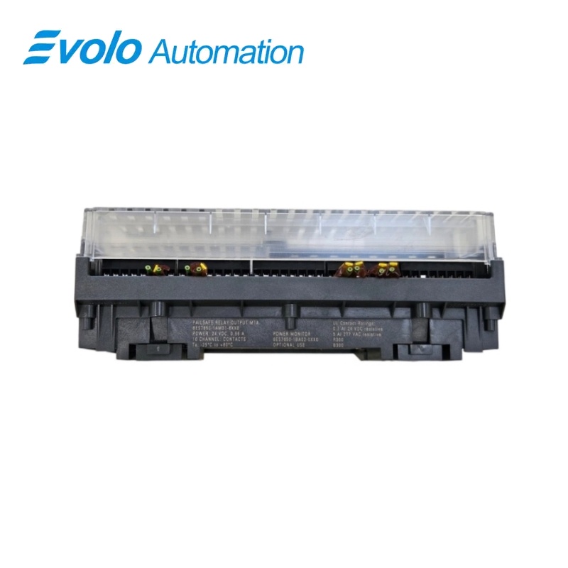
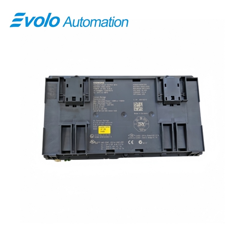
Siemens SIMATIC PCS 7 Redundant F-DO10 Relay MTA 6ES7650-1AM31-6XX0
Manufacturer: Siemens
Condition: Brand New
Lead Time: In Stock
Origin: Germany
Warranty: 12 Months
Email: [email protected]
whatsApp: +86-18150117685
- Overview
- Product Overview
- Key Functions
- Official Specifications
- Frequently Asked Questions
- Compatibility & Ordering Notes
- Hot Selling Models
- Recommended Products
Overview
Siemens • SIMATIC PCS 7 / ET 200M
6ES7650-1AM31-6XX0 SIMATIC PCS 7 Redundant F-DO10 Relay MTA
The redundant F-DO10 relay MTA connects an ET 200M fail-safe ten-channel output module to relay field circuits with redundant fused supply inputs and LED indication.
At a Glance
| Brand | Siemens |
|---|---|
| Model | 6ES7650-1AM31-6XX0 |
| Product Type | Ten-channel fail-safe relay-output marshalled termination assembly |
| Core Function | Terminates redundant fail-safe relay outputs from an ET 200M F-DO10 module |
| Application or Compatible Series | SIMATIC PCS 7 ET 200M safety stations using 6ES7326-2BF10-0AB0 |
Exact Identification
Match 6ES7650-1AM31-6XX0 character by character and confirm the complete SIMATIC PCS 7 Redundant F-DO10 Relay MTA designation.
Interface Arrangement
Confirm the installed supply, ports, field connections and required accessories before wiring the replacement.
Configuration Check
Preserve the approved engineering project, network parameters and application data used by the installed system.
Product Overview
The redundant F-DO10 relay MTA connects an ET 200M fail-safe ten-channel output module to relay field circuits with redundant fused supply inputs and LED indication.
Ten relay channels interface the approved ET 200M F-DO10 safety module to field circuits. The MTA supports the documented redundant I/O arrangement for PCS 7 safety applications. Fused redundant supplies and LED indications support channel and power troubleshooting.
Key Functions
Fail-Safe Output Termination
Ten relay channels interface the approved ET 200M F-DO10 safety module to field circuits.
Redundant Module Connection
The MTA supports the documented redundant I/O arrangement for PCS 7 safety applications.
Serviceable Power Distribution
Fused redundant supplies and LED indications support channel and power troubleshooting.
Official Specifications
| Compatible ET 200M Module | 6ES7326-2BF10-0AB0 |
|---|---|
| DC Output Range | 24 to 150 V DC |
| AC Output Range | 120 to 220 V AC |
| Supply Voltage | 24 V DC |
| Supply Current | 0.56 A |
| Relay Contact Rating | 5 A at 230 V AC or 24 V DC |
| Ambient Temperature | -25 to +70 °C |
| Temperature Code | T4 |
| Power-Monitor Option Rating | 24 V DC, 0.5 A |
| Power Inputs | Redundant and fused |
| Status Indication | LED displays |
| Net Weight | 0.955 kg |
| Packaging Dimensions | 26 x 20.3 x 15 cm |
Frequently Asked Questions
Which fail-safe output module is paired with 6ES7650-1AM31-6XX0?
Use the specified ET 200M ten-channel fail-safe output module.
How many relay circuits can I terminate on 6ES7650-1AM31-6XX0?
The assembly provides ten relay-output channels.
Which field-voltage ranges are supported by 6ES7650-1AM31-6XX0?
The relay outputs cover 24 to 150 V DC and 120 to 220 V AC within all contact ratings.
What current limit applies to the relay contacts of 6ES7650-1AM31-6XX0?
Keep each relay circuit within the documented 5 A contact rating and the connected load category.
How should redundant power be connected to 6ES7650-1AM31-6XX0?
Wire both approved 24 V DC feeds through the documented fused inputs and verify the LED indications.
What safety data should be preserved before replacing 6ES7650-1AM31-6XX0?
Retain the F-system project, safety signature, proof-test record, channel assignment and relay-load documentation.
What validation is required after installing 6ES7650-1AM31-6XX0?
Perform the authorized safety-function test, including both module paths, every relay channel, diagnostics and de-energized behavior.
Compatibility & Ordering Notes
Compatibility Checklist
- Use only with the documented ET 200M fail-safe output module and approved PCS 7 safety architecture.
- Keep every AC and DC load within the relay ratings and preserve isolation requirements.
- Complete the site safety validation before returning the protected process to service.