EN




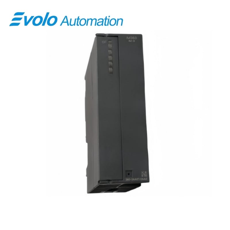
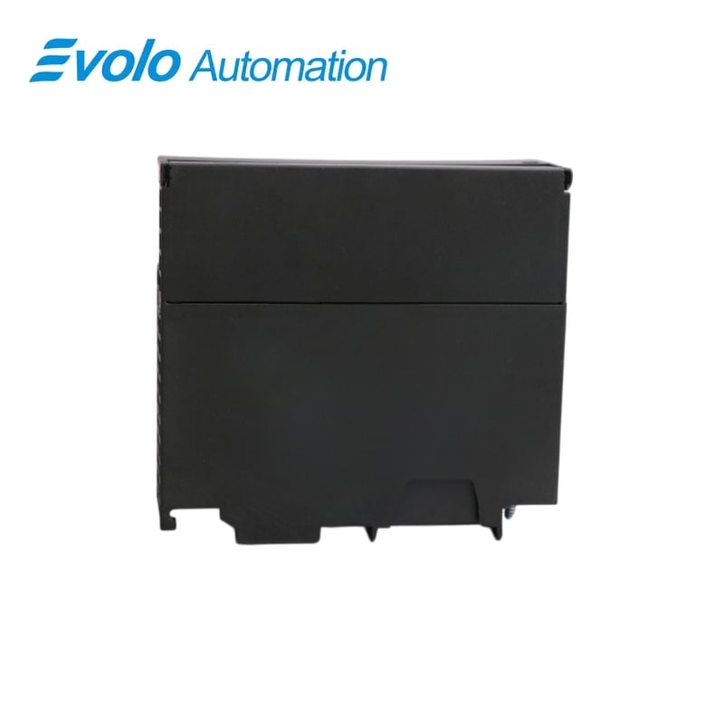
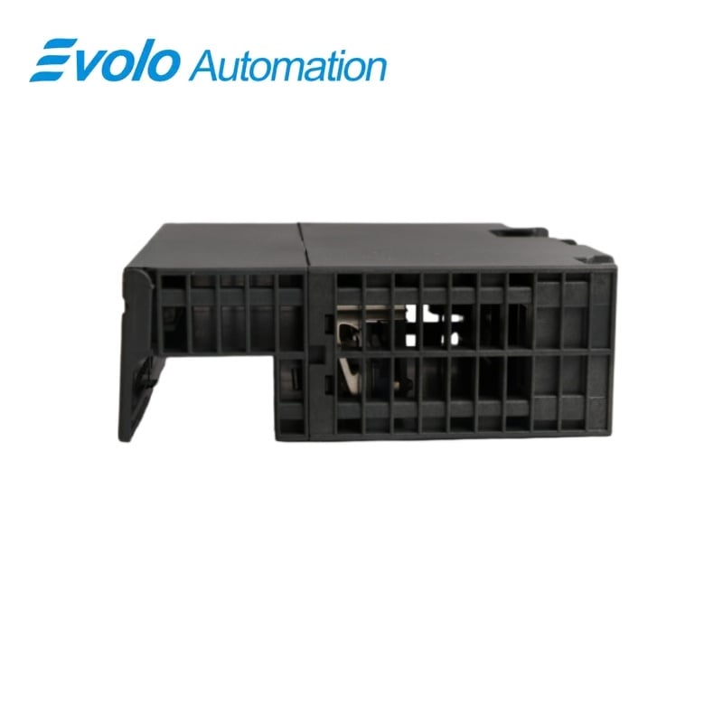
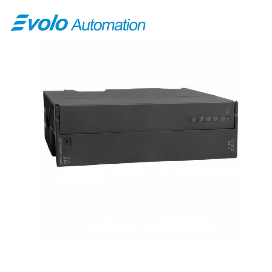
Siemens 6ES7360-3AA01-0AA0 SIMATIC S7-300 IM 360 Central-Rack Interface
Manufacturer: Siemens
Condition: Brand New
Lead Time: In Stock
Origin: Germany
Warranty: 12 Months
Email: [email protected]
whatsApp: +86-18150117685
- Overview
- Hot Selling Models
- Recommended Products
Overview
- Confirm the CPU supports multiple racks.
- Place the sender in central-rack slot 3 before the first signal module.
- Use IM 361 receivers for racks 1–3.
- Keep each interface-to-interface cable span within 10 m.
- Calculate the separate backplane current budgets for the CPU and expansion racks.
6ES7360-3AA01-0AA0 SIMATIC S7-300 IM 360 Central-Rack Interface
An IM 360 send interface for rack 0, supporting up to three expansion racks through matching IM 361 receiver interfaces.
At a Glance
| Brand | Siemens |
|---|---|
| Model | 6ES7360-3AA01-0AA0 |
| Product Type | IM 360 send interface |
| Core Function | Extending the backplane bus to expansion racks |
| Application | Central rack of a supported S7-300 assembly |
Central-rack sender
The IM 360 occupies the sending position in rack 0.
Expansion receivers
IM 361 interfaces receive the connection in racks 1–3.
Defined cable span
Each interface-to-interface connection can be up to 10 m long.
Product Overview
6ES7360-3AA01-0AA0 extends the backplane bus of a supported S7-300 CPU from the central rack to expansion racks, using IM 361 receiving interfaces and the corresponding connecting cable.
The arrangement supports up to three expansion racks and routes the communication bus, while the SF indication helps identify a missing connection cable or a receiver that is switched off.
Key Functions
Send the rack-extension connection
The IM 360 serves the central-rack side of an IM 360/IM 361 multi-rack arrangement.
Route data across the linking cable
Connecting cable 368 links the sender to the next receiver, with a maximum 10 m span to the next interface.
Indicate an interrupted extension arrangement
The SF group-error indication lights when the connecting cable is absent or the IM 361 is switched off.
Official Specifications
| Expansion Rack Capacity | Up to 3 racks |
|---|---|
| Interfaces per CPU | Maximum 1 IM 360 |
| Maximum Cable Length to Next Interface | 10 m |
| Backplane Supply Current | 350 mA maximum from 5 V DC |
| Typical Power Dissipation | 2 W |
| Error Indication | SF group-error LED |
| Dimensions (W × H × D) | 40 × 125 × 120 mm |
| Approximate Weight | 225 g |
Frequently Asked Questions
Which rack receives 6ES7360-3AA01-0AA0 in a multi-rack S7-300 station?
The send interface is installed in the central rack, rack 0.
Which receiving interface should I pair with 6ES7360-3AA01-0AA0?
Use IM 361 receiving interfaces in expansion racks 1 to 3.
Can 6ES7360-3AA01-0AA0 add expansion racks to a CPU 312 or CPU 312C?
Those CPU types permit only a single-rack configuration.
Where should 6ES7360-3AA01-0AA0 sit relative to the signal modules?
The interface occupies slot 3, to the left of the first signal module.
Which cable lengths are available for the connection from 6ES7360-3AA01-0AA0?
The listed cable options are 1 m, 2.5 m, 5 m and 10 m.
Why might the SF LED on 6ES7360-3AA01-0AA0 remain lit?
The group-error indication lights if the connecting cable is missing or the IM 361 is switched off.
Does 6ES7360-3AA01-0AA0 route the communication bus as part of the extension?
The IM 360 connection includes the communication bus.