EN




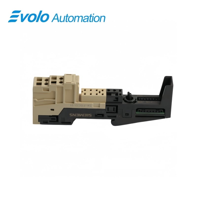
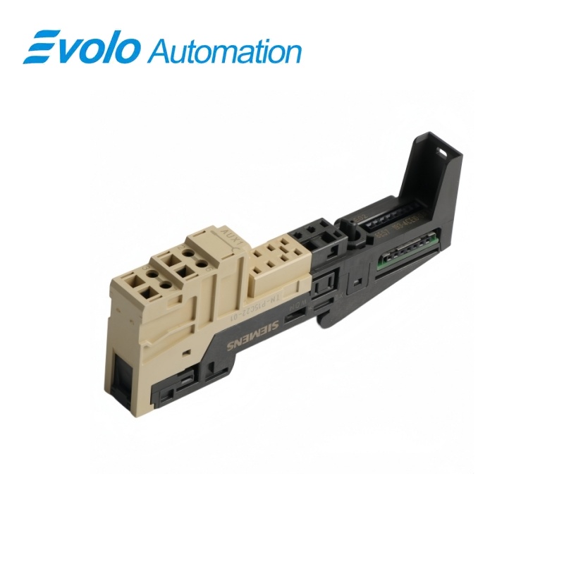
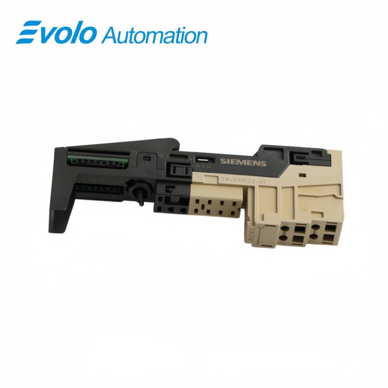
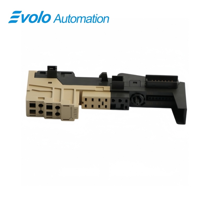
Siemens 6ES7193-4CE10-0AA0 SIMATIC ET 200S TM-P15C22-01 Terminal Module
Manufacturer: Siemens
Condition: Brand New
Lead Time: In Stock
Origin: Germany
Warranty: 12 Months
Email: [email protected]
whatsApp: +86-18150117685
- Overview
- Hot Selling Models
- Recommended Products
Overview
- Select the correct ET 200S power module for the TM-P base.
- Plan the next power potential group boundary.
- Provide AUX1 field access elsewhere if the installation needs it.
- Allow service space around the base locking mechanism.
SIEMENS SIMATIC ET 200S
6ES7193-4CE10-0AA0 SIMATIC ET 200S TM-P15C22-01 Terminal Module
A compact spring-terminal base for an ET 200S power module with four connections and a continuous AUX1 bus.
At a Glance
| Brand | Siemens |
|---|---|
| Model | 6ES7193-4CE10-0AA0 |
| Product Type | Power module base |
| Core Function | Potential group infeed |
| Application | ET 200S power distribution |
Four spring connections
The 2 × 2 layout receives the power-module wiring without adding an auxiliary terminal row.
Continuous auxiliary path
AUX1 passes through the power group boundary without a local terminal tap.
Compact power position
The base measures 15 × 119.5 × 43 mm and weighs approximately 55 g.
Product Overview
6ES7193-4CE10-0AA0 is the TM-P15C22-01 Cage Clamp base for power-module positions in a SIMATIC ET 200S station.
It allows a new electronic-module power section to begin while keeping the auxiliary bus continuous, using a shorter four-connection housing without A4/A8 access.
Key Functions
Introduce a new electronic supply section
The inserted power module feeds the downstream power buses up to the next TM-P position.
Preserve auxiliary potential continuity
The continuous AUX1 bus links to the group on the left independently of the new power-module position.
Wire the compact clamp layout
Four spring connection positions accept 11 mm stripped conductor ends using a 3 mm opening tool.
Official Specifications
| Terminal arrangement | 2 × 2 connections |
|---|---|
| Connection technology | Spring terminals (Cage Clamp) |
| AUX1 routing | Continuous to the potential group on the left |
| AUX1 terminal access | No terminal access |
| Bare solid and flexible conductor range | 0.14–2.5 mm² |
| Flexible conductor range with ferrule | 0.14–1.5 mm² |
| Wire stripping length | 11 mm |
| Conductors per connection | 1; alternatively 2 totaling up to 1.5 mm² in a shared ferrule |
| Maximum wire insulation diameter | 3.1 mm at 1.5 mm²; 3.8 mm at 2.5 mm² |
| Wiring tool | Screwdriver with 3 mm blade |
| Dimensions (W × H × D) | 15 × 119.5 × 43 mm |
| Approximate module weight | 55 g |
Frequently Asked Questions
Can 6ES7193-4CE10-0AA0 start a new power section without cutting AUX1?
Yes, its TM-P infeed function starts a power potential group while the AUX1 bus remains continuous.
Does 6ES7193-4CE10-0AA0 support Continuous auxiliary path for mobile equipment?
The TM-P15C22-01 uses a four-connection layout with no local access to the auxiliary bus.
Which opening should I use for the wire when wiring 6ES7193-4CE10-0AA0?
Insert the prepared conductor into the lower square opening while operating the spring release through the upper round opening.
Can I put 6ES7193-4CE10-0AA0 under a normal 15 mm electronic I/O module?
This TM-P base is intended for power modules, so electronic I/O positions require the appropriate TM-E base.
How much height should I reserve for 6ES7193-4CE10-0AA0?
The terminal module body is 119.5 mm high, 15 mm wide and 43 mm deep.
What supply arrangement continues after 6ES7193-4CE10-0AA0 in the station?
The power-module infeed supplies the electronic modules until the next TM-P terminal-module boundary.
Can I remove 6ES7193-4CE10-0AA0 while leaving its field wiring connected?
Disconnect the base wiring and switch off the relevant supply before releasing and removing the terminal module.